содержание .. 20 21 22 23 ..
Nissan Primera P12. Manual - part 22
TROUBLE DIAGNOSIS
ATC-81
C
D
E
F
G
H
I
K
L
M
A
B
ATC
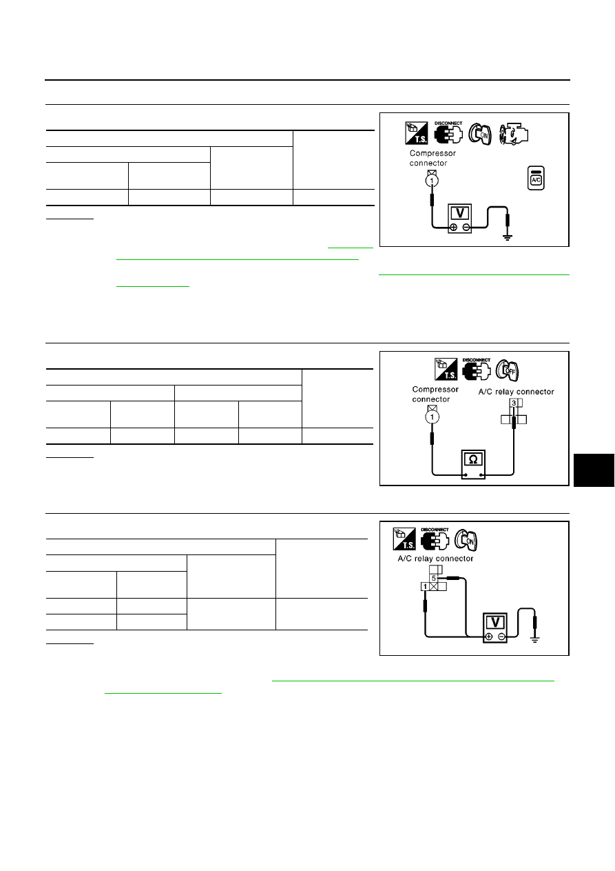
1.
CHECK POWER SUPPLY FOR COMPRESSOR
Disconnect compressor harness connector.
OK or NG
OK
>> Check magnet clutch coil.
1. If NG, replace magnet clutch. Refer to
"Compressor Clutch (Except F9Q Engine Models)"
.
2. Go to self-diagnosis function confirmation procedure
ATC-49, "FUNCTION CONFIRMATION
and perform self-diagnosis STEP-4. Confirm that magnet clutch operation is in
good order.
NG
>> Disconnect A/C relay. And GO TO 2.
2.
CHECK CIRCUIT CONTINUITY BETWEEN A/C RELAY AND COMPRESSOR
OK or NG
OK
>> Check harness for short. And GO TO 3.
NG
>> Repair harness or connector.
3.
CHECK POWER SUPPLY FOR A/C RELAY
Disconnect A/C relay.
OK or NG
OK
>> GO TO 4.
NG
>> Check power supply circuit and 10A (No.15 fuse,
located in the fuse block). Refer to
PG-10, "IGNITION POWER SUPPLY — IGNITION SW. IN
.
●
If OK, check for open circuit in wiring harness. Repair or replace as necessary.
●
If NG, replace fuse and check wiring harness for short circuit. Repair or replace as necessary.
Terminal
Voltage
(+)
(
−
)
Compressor
connector
Terminal No.
(Wire color)
E32
1 (L/R)
Ground
Battery voltage
RJIA0295E
Terminal
Continuity
(+)
(
−
)
A/C relay con-
nector
Terminal No.
(Wire color)
Compressor
connector
Terminal No.
(Wire color)
E17
3 (L/R)
E32
1 (L/R)
Yes
RJIA0793E
Terminal
Voltage
(+)
(
−
)
A/C relay con-
nector
Terminal No.
(Wire color)
E17
1 (L/Y)
Ground
Battery voltage
E17
5 (L/Y)
RJIA0794E