содержание .. 795 796 797 798 ..
Nissan Tiida C11. Manual - part 797
FRONT SUSPENSION ASSEMBLY
FSU-11
< REMOVAL AND INSTALLATION >
C
D
F
G
H
I
J
K
L
M
A
B
FSU
N
O
P
REMOVAL AND INSTALLATION
FRONT SUSPENSION ASSEMBLY
Removal and Installation
INFOID:0000000001716901
REMOVAL
1.
Separate intermediate shaft from steering gear pinion shaft. Refer to
ST-9, "Removal and Installation"
.
2.
Remove front tires from vehicle using a power tool.
3.
Remove wheel sensor from steering knuckle. Refer to
BRC-182, "Removal and Installation"
CAUTION:
Do not pull on wheel sensor harness.
4.
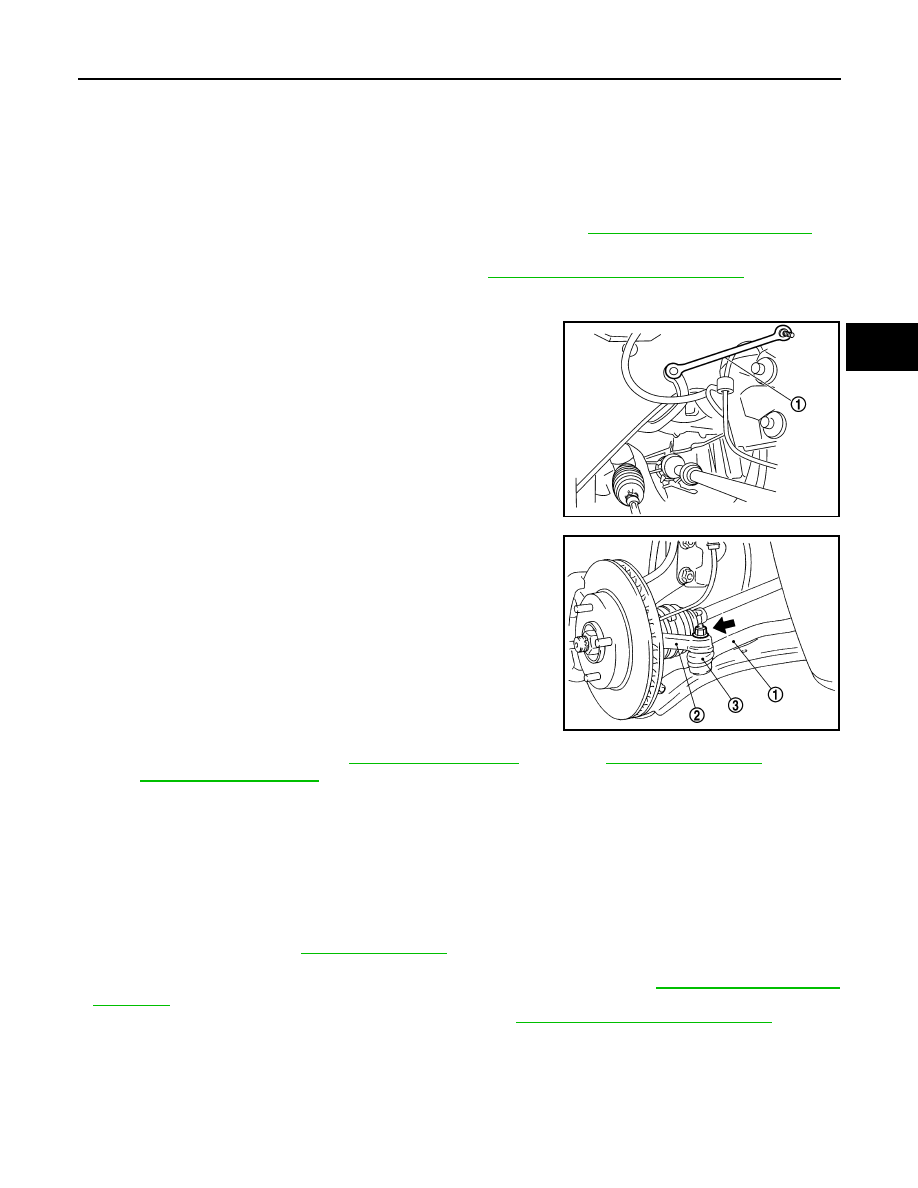
Remove the nut on the upper side of stabilizer connecting rod
(1) with a power tool, and then remove stabilizer connecting rod
(1) from strut assembly.
5.
Loosen steering outer socket (1) nut.
6.
Remove steering outer socket (1) from steering knuckle (2) so
as not to damage ball joint boot (3) using Tool.
CAUTION:
Temporarily tighten the nut to prevent damage to threads
and to prevent the Tool from suddenly coming off.
7.
Remove rear torque rod. Refer to
(HR16DE),
(HR18DE)
8.
Remove transverse link ball joint nut and bolt. Then, remove transverse link from steering knuckle.
9.
Set jack under front suspension member.
10. Remove upper side bolts of upper link.
11. Remove the bolts of member stay, and then remove member stay from vehicle.
12. Gradually lower a jack to remove front suspension assembly.
INSTALLATION
Installation is in the reverse order of removal.
• For tightening torque, refer to
.
• Perform final tightening of each of parts (rubber bushing), under unladen conditions, which were removed
when removing front suspension assembly. Check wheel alignment. Refer to
.
• Check wheel sensor harness for proper connection. Refer to
BRC-182, "Removal and Installation"
.
SGIA1297E
Tool number
: HT72520000 (J-25730-A)
SGIA1298E