Nissan Tiida C11. Manual - part 785


  Главная      Nissan     Nissan Tiida C11 - Service Manual


поиск по сайту            


содержание   ..  783  784  785  786   ..


Nissan Tiida C11. Manual - part 785


FRONT WHEEL HUB AND KNUCKLE

FAX-5

< ON-VEHICLE MAINTENANCE >

C

E

F

G

H

I

J

K

L

M

A

B

FAX

N

O

P

ON-VEHICLE MAINTENANCE

FRONT WHEEL HUB AND KNUCKLE

On-Vehicle Inspection and Service

INFOID:0000000001716786

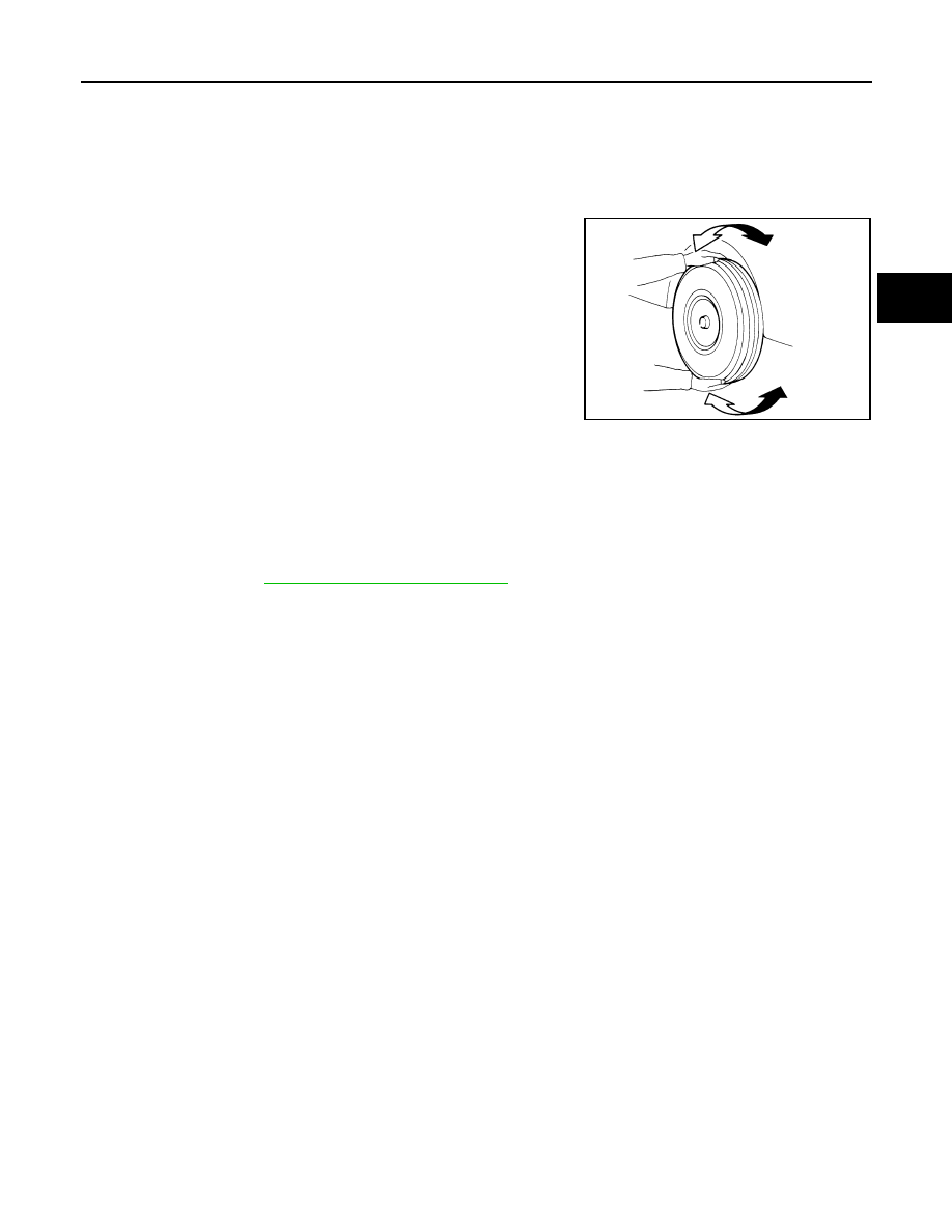
• Check the axle and suspension parts for excessive play, wear, or damage.
• Shake each front wheel to check for excessive play as shown.

FRONT WHEEL BEARING INSPECTION

• Move wheel hub and bearing assembly in the axial direction by hand. Make sure the axial end play is within

specification. 

• Check that the wheel hub bearing operates smoothly.
• Replace the wheel hub assembly if the axial end play exceeds specification, or if the wheel bearing does not

turn smoothly. Refer to 

FAX-7, "Removal and Installation"

 .

CAUTION:

The wheel hub assembly does not require maintenance. If any of the following symptoms are noted,
replace the wheel hub assembly.
• Growling noise is emitted from the wheel hub bearing during operation.
• Wheel hub bearing drags or turns roughly.

SMA525A

Axial end play

: 0.05 mm (0.002 in) or less

FAX-6

< ON-VEHICLE MAINTENANCE >

FRONT DRIVE SHAFT

FRONT DRIVE SHAFT

On-Vehicle Inspection and Service

INFOID:0000000001716790

• Check drive shaft mounting point and joint for looseness and other damage.
• Check boot for cracks and other damage.
Replace or repair components as necessary. Refer to 

FAX-10, "Removal and Installation (Left Side)"

 , 

FAX-11,

"Removal and Installation (Right Side)"

 , 

FAX-14, "Disassembly and Assembly (Left Side)"

  or 

FAX-19, "Disas-

sembly and Assembly (Right Side)"

 .

CAUTION:

Replace entire drive shaft assembly when noise or vibration occur from drive shaft.

FRONT WHEEL HUB AND KNUCKLE

FAX-7

< REMOVAL AND INSTALLATION >

C

E

F

G

H

I

J

K

L

M

A

B

FAX

N

O

P

REMOVAL AND INSTALLATION

FRONT WHEEL HUB AND KNUCKLE

Removal and Installation

INFOID:0000000001716789

COMPONENT

REMOVAL

1.

Remove wheel and tire using power tool. Refer to 

WT-6, "Rotation"

 .

2.

Without disassembling the hydraulic lines, remove the torque member bolts using power tool. Then repo-
sition the torque member and brake caliper assembly aside with wire. Refer to 

BR-25, "Removal and

Installation of Brake Caliper Assembly"

 .

CAUTION:

Do not depress brake pedal while brake caliper is removed.

3.

Put alignment marks on disc rotor and wheel hub and bearing
assembly, then remove disc rotor.

4.

Remove wheel sensor from steering knuckle. Refer to 

BRC-182, "Removal and Installation"

 .

CAUTION:

Do not pull on wheel sensor harness.

1.

Drive shaft

2.

Steering knuckle

3.

Splash guard

4.

Wheel hub and bearing assembly

5.

Cotter pin

WDIA0366E

SDIA1480E

FAX-8

< REMOVAL AND INSTALLATION >

FRONT WHEEL HUB AND KNUCKLE

5.

Loosen steering outer socket (1) nut.

6.

Remove steering outer socket (1) from steering knuckle (2) so
as not to damage ball joint (3) boot using Tool.

CAUTION:

Temporarily leave the outer socket nut installed to prevent
damage to threads and to prevent the ball joint remover or
suitable tool from suddenly coming off.

7.

Remove transverse link ball joint nut and bolt. Then, remove transverse link from steering knuckle.

8.

Remove cotter pin, then loosen hub lock nut using power tool.

CAUTION:

Temporarily leave the hub lock nut installed to prevent damage to threads.

9.

Separate the drive shaft from the wheel hub and bearing assem-
bly by lightly tapping the end of the drive shaft using a hammer
or suitable tool, and then remove hub lock nut. 
NOTE:
Use a suitable puller if wheel hub and bearing assembly and
drive shaft cannot be separated after performing the above pro-
cedure.

10. Remove the drive shaft from the wheel hub and bearing assem-

bly and support the drive shaft.

CAUTION:

• Do not apply an excessive angle to drive shaft joint when

removing from the wheel hub and bearing assembly,

• Do not excessively extend slide joint.
• Do not allow drive shaft to hang down. Support the entire drive shaft.

11. Remove wheel hub and bearing assembly bolts, and then remove splash guard and wheel hub and bear-

ing assembly from steering knuckle.

12. Remove nuts and bolts, and then remove steering knuckle from

strut assembly.

INSPECTION AFTER REMOVAL

Wheel Hub and Knuckle Inspection

Check for any deformity, cracks, or other damage on the wheel hub assembly and knuckle, replace if neces-
sary.

CAUTION:

The wheel hub assembly does not require maintenance. If any of the following symptoms are noted,
replace the wheel hub assembly.
• Growling noise is emitted from the wheel hub bearing during operation.
• Wheel hub bearing drags or turns roughly.

Ball Joint Inspection

Check boots of transverse link and steering outer socket ball joint for breakage, axial play, and torque. Refer to

FSU-13, "Removal and Installation"

  transverse link and 

ST-14, "Disassembly and Assembly"

  steering outer

socket ball joint.

INSTALLATION

Tool number

: HT72520000 (J-25730-A)

SGIA1298E

SDIA1821E

WDIA0367E


содержание   ..  783  784  785  786   ..