Nissan Tiida C11. Manual - part 763


  Главная      Nissan     Nissan Tiida C11 - Service Manual


поиск по сайту            


содержание   ..  761  762  763  764   ..


Nissan Tiida C11. Manual - part 763


EXL-50

< COMPONENT DIAGNOSIS >

PARKING LAMP CIRCUIT

3.

Check continuity between the IPDM E/R harness connector (A) and the front combination lamp harness
connector (B).

4.

Check continuity between the IPDM E/R harness connector (A) and the license plate lamp harness con-
nector (B)(hatchback) or (C)(sedan).

5.

Check continuity between the IPDM E/R harness connector (A) and the rear combination lamp harness
connector (B).

Does continuity exist?

YES

>> GO TO 4

NO

>> Repair the daytime light relay, harness or connectors.
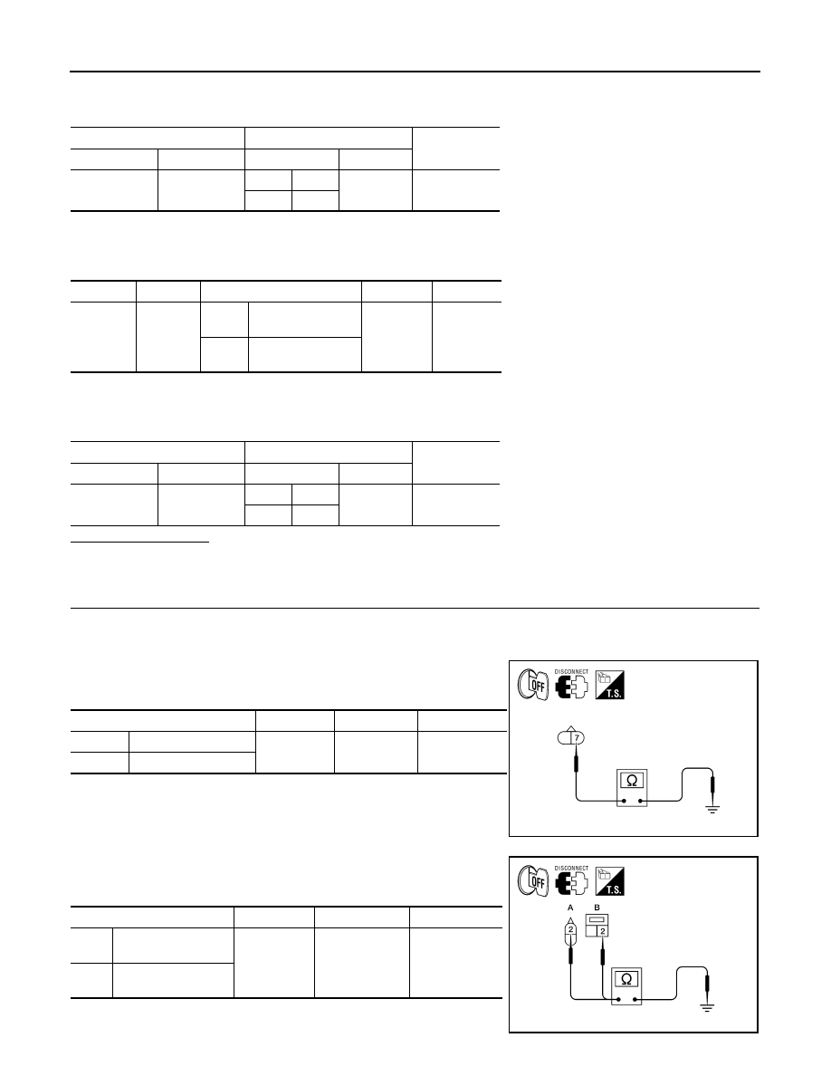
4.

CHECK PARKING LAMP GROUND CIRCUIT

1.

Turn ignition switch OFF.

2.

Disconnect the front combination lamp connectors, rear combination lamp connectors or license plate
lamp connectors.

3.

Check continuity between the front combination lamp harness
connector terminal and ground.

4.

Check continuity between the license plate lamp harness con-
nector terminal and ground.

A

B

Continuity

Connector

Terminal

Connector

Terminal

E45

27

LH

E53

6

Yes

RH

B54

Connector

Terminal

Connector

Terminal

Continuity

A: E45

29

LH

B: B87 (hatchback)
C: B62 (sedan)

1

Yes

RH

B: B88 (hatchback)
C: B63 (sedan)

A

B

Continuity

Connector

Terminal

Connector

Terminal

E45

29

LH

B80

4

Yes

RH

B59

Front combination lamp connector

Terminal

Continuity

LH

E53

7

Ground

Yes

RH

E54

WKIA5509E

License plate lamp connector

Terminal

Continuity

LH

A: B87 (hatchback)
B: B62 (sedan)

2

Ground

Yes

RH

A: B88 (hatchback)
B: B63 (sedan)

WKIA6035E

PARKING LAMP CIRCUIT

EXL-51

< COMPONENT DIAGNOSIS >

C

D

E

F

G

H

I

J

K

M

A

B

EXL

N

O

P

5.

Check continuity between the rear combination lamp harness
connector terminal and ground.

Does continuity exist?

YES

>> Inspect the parking lamp bulb.

NO

>> Repair the harness.

Connector

Terminal

Continuity

LH

B80

1

Ground

Yes

RH

B59

PKIC1029E

EXL-52

< COMPONENT DIAGNOSIS >

TURN SIGNAL LAMP CIRCUIT

TURN SIGNAL LAMP CIRCUIT

Description

INFOID:0000000001523271

The BCM monitors inputs from the combination switch to determine when to activate the turn signals. The
BCM outputs voltage directly to the left and right turn signals during turn signal operation or both during hazard
warning operation. The BCM sends a turn signal indicator request to the combination meter via the CAN com-
munication lines. 
The BCM performs the fast flasher operation (fail-safe) if any bulb or harness of the turn signal lamp circuit is
open.
NOTE:
Turn signal lamps blink at normal speed when using the hazard warning lamp.

Component Function Check

INFOID:0000000001523272

1.

CHECK TURN SIGNAL LAMP

CONSULT-III

1.

Select "FLASHER" of BCM (FLASHER) active test item.

2.

With test items operating, check that the turn signal lamp blinks.

Does the turn signal lamp blink?

YES

>> Turn signal lamp circuit is normal.

NO

>> Refer to 

EXL-52, "Diagnosis Procedure"

.

Diagnosis Procedure

INFOID:0000000001523273

1.

CHECK TURN SIGNAL LAMP BULB

Check the applicable lamp bulb to be sure the proper bulb standard is in use and the bulb is not open.
Is the bulb OK?

YES

>> GO TO 2

NO

>> Replace the bulb.

2.

CHECK TURN SIGNAL LAMP OUTPUT VOLTAGE

1.

Turn the ignition switch OFF.

2.

Disconnect the front combination lamp connector, the rear combination lamp connector and the side turn
signals.

3.

Turn the ignition switch ON.

4.

With the turn signal switch operating, check voltage between the BCM harness connector M20 and
ground.

Is the measurement value normal?

YES

>> GO TO 3

NO

>> Replace BCM.

LH

: Turn signal lamp LH blinking 

RH

: Turn signal lamp RH blinking 

OFF

: The turn signal lamp OFF

(+)

(

)

Voltage

Connector

Terminal

M20 

LH

65

Ground

RH

66

PKID0926E

TURN SIGNAL LAMP CIRCUIT

EXL-53

< COMPONENT DIAGNOSIS >

C

D

E

F

G

H

I

J

K

M

A

B

EXL

N

O

P

3.

CHECK TURN SIGNAL LAMP CIRCUIT FOR OPEN 

1.

Turn the ignition switch OFF.

2.

Disconnect BCM connector.

3.

Check the continuity between the BCM harness connector M20 and the front combination lamps.

4.

Check the continuity between the BCM harness connector M20 and the side turn signals.

5.

Check the continuity between the BCM harness connector M20 and the rear combination lamps.

Does continuity exist?

YES

>> GO TO 4

NO

>> Repair the harnesses or connectors.

4.

CHECK TURN SIGNAL LAMP SHORT CIRCUIT

Check continuity between the BCM harness connector M20 and ground.

Does continuity exist?

YES

>> Repair the harnesses or connectors.

NO

>> GO TO 5

5.

CHECK TURN SIGNAL LAMP GROUND CIRCUIT

Check continuity between the front combination lamp, the rear combination lamp or the side turn signal and
ground.

A

B

Continuity

Connector

Terminal

Connector

Terminal

Front LH

M20

65

E29 (hallogen headlamps)

4

Yes

E25 (xenon headlamps)

5

Front RH

66

E30 (hallogen headlamps)

4

E26 (xenon headlamps)

5

A

B

Continuity

Connector

Terminal

Connector

Terminal

Side LH

M20

65

E56

1

Yes

Side RH

66

E57

A

B

Continuity

Connector

Terminal

Connector

Terminal

Rear LH

M20

65

B80

6

Yes

Rear RH

66

B59

Connector

Terminal

Continuity

LH

M20

65

Ground

No

RH

66

Connector

Terminal

Continuity


содержание   ..  761  762  763  764   ..