содержание .. 758 759 760 761 ..
Nissan Tiida C11. Manual - part 760
EXL-38
< COMPONENT DIAGNOSIS >
HEADLAMP (LO) CIRCUIT
Is the measurement value normal?
YES
>> GO TO 4
NO
>> GO TO 3
3.
CHECK HEADLAMP (LO) CIRCUIT FOR OPEN
1.
Turn the ignition switch OFF.
2.
Disconnect IPDM E/R connector.
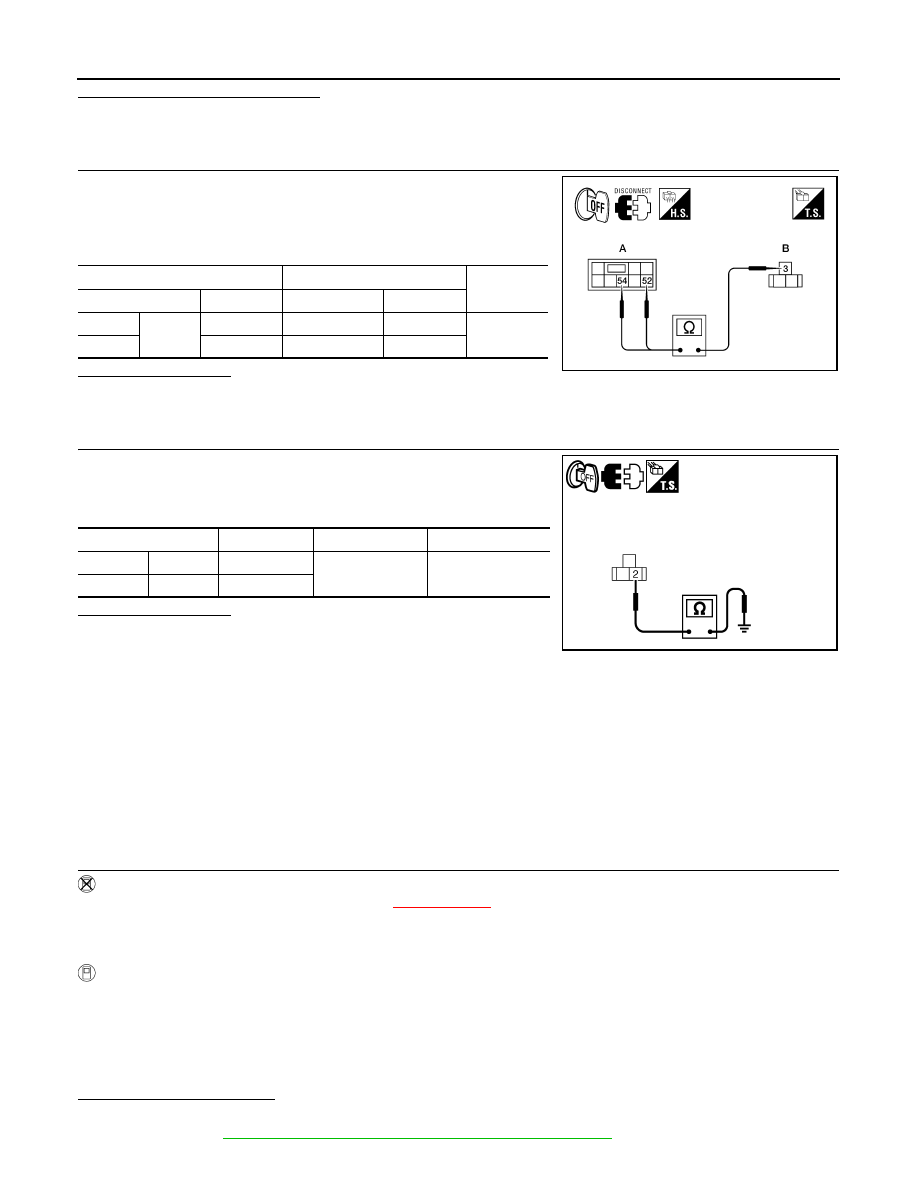
3.
Check continuity between the IPDM E/R harness connector and
the front combination lamp harness connector.
Does continuity exist?
YES
>> GO TO 4
NO
>> Repair the harnesses or connectors.
4.
CHECK HEADLAMP (LO) GROUND CIRCUIT
1.
Disconnect the front combination lamp connector.
2.
Check continuity between the front combination lamp harness
connector terminal and ground.
Does continuity exist?
YES
>> Inspect the headlamp bulb.
NO
>> Repair the harness.
HEADLAMP (XENON)
HEADLAMP (XENON) : Description
INFOID:0000000001527568
The IPDM E/R (intelligent power distribution module engine room) controls the headlamp low relay based on
inputs from the BCM via the CAN communication lines. When the headlamp low relay is energized, power
flows through fuses 40 and 41, located in the IPDM E/R. Power then flows to the front combination lamps to
the headlamp low beam.
HEADLAMP (XENON) : Component Function Check
INFOID:0000000001527569
1.
CHECK HEADLAMP (LO) OPERATION
WITHOUT CONSULT-III
1.
Start IPDM E/R auto active test. Refer to
XX-XX, "*****"
.
2.
Check that the headlamp is turned ON.
NOTE:
HI/LO is repeated 1 second each when using the IPDM E/R auto active test.
CONSULT-III
1.
Select "EXTERNAL LAMP" of IPDM E/R active test item.
2.
With operating the test items, check that the headlamp is turned ON.
Is the headlamp turned ON?
YES
>> Headlamp (LO) is normal.
NO
>> Refer to
EXL-39, "HEADLAMP (XENON) : Diagnosis Procedure"
A
B
Continuity
Connector
Terminal
Connector
Terminal
LH
E47
52
E25
3
Yes
RH
54
E26
3
WKIA5471E
Connector
Terminal
—
Continuity
LH
E25
2
Ground
Yes
RH
E26
2
PKIC0961E
LO
: Headlamp ON
OFF
: Headlamp OFF