Nissan Tiida C11. Manual - part 717


  Главная      Nissan     Nissan Tiida C11 - Service Manual


поиск по сайту            


содержание   ..  715  716  717  718   ..


Nissan Tiida C11. Manual - part 717


EM-220

< DISASSEMBLY AND ASSEMBLY >

[MR18DE]

ENGINE UNIT

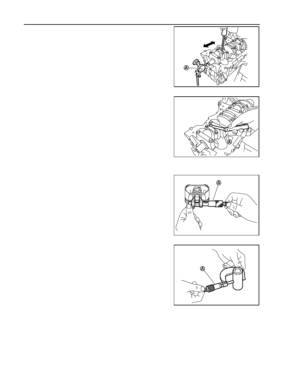
• Measure the clearance between thrust bearings and crankshaft

arm when crankshaft is moved fully forward or backward with a dial
indicator (A).

• If the measured value exceeds the limit, replace thrust bearings,

and measure again. If it still exceeds the limit, replace crankshaft
also.

CONNECTING ROD SIDE CLEARANCE

• Measure the side clearance between connecting rod and crank-

shaft arm with a feeler gauge (A).

• If the measured value exceeds the limit, replace connecting rod,

and measure again. If it still exceeds the limit, replace crankshaft
also.

PISTON TO PISTON PIN OIL CLEARANCE

Piston Pin Hole Diameter 

Measure the inner diameter of piston pin hole with an inside
micrometer (A).

Piston Pin Outer Diameter 

Measure the outer diameter of piston pin with a micrometer (A).

Piston to Piston Pin Oil Clearance

(Piston to piston pin oil clearance) = (Piston pin hole diameter) – (Piston pin outer diameter)

• If oil clearance is out of the standard, replace piston and piston pin assembly. 
• When replacing piston and piston pin assembly, rfollow the "Piston to Cylinder Bore Clearance" procedure.

NOTE:
• Piston is available together with piston pin as assembly.

Standard

: 0.10 - 0.26 mm (0.0039 - 0.0102 in)

Limit

: 0.30 mm (0.012 in)

PBIC3252J

Standard

: 0.20 - 0.35 mm (0.0079 - 0.0138 in)

Limit

: 0.40 mm (0.0157 in)

PBIC3251J

Standard: 19.993 - 19.999 mm (0.7871 - 0.7874 in)

PBIC3265J

Standard: 19.989 - 19.995 mm (0.7870 - 0.7872 in)

PBIC3266J

Standard: 0.002 - 0.006 mm (0.0001 - 0.0002 in)

ENGINE UNIT

EM-221

< DISASSEMBLY AND ASSEMBLY >

[MR18DE]

C

D

E

F

G

H

I

J

K

L

M

A

EM

N

P

O

• Piston pin (piston pin hole) grade is provided only for the parts installed at the plant. For service parts, no

grades can be selected. (Only grade “0” is available.) 

PISTON RING SIDE CLEARANCE

• Measure the side clearance of piston ring and piston ring groove

with a feeler gauge (A).

• If the measured value exceeds the limit, replace piston ring, and measure again. If it still exceeds the limit,

replace piston also.

PISTON RING END GAP

• Make sure that cylinder bore inner diameter is within specification. 
• Lubricate with new engine oil to piston (1) and piston ring (2), and

then insert (A) piston ring until middle of cylinder (B) with piston,
and measure piston ring end gap with a feeler gauge (C).

• If the measured value exceeds the limit, replace piston ring, and measure again. If it still exceeds the limit,

re-bore cylinder and use oversized piston and piston rings.

CONNECTING ROD BEND AND TORSION

Standard:

Top ring

: 0.04 - 0.08 mm (0.002 - 0.003 in)

2nd ring

: 0.03 - 0.07 mm (0.001 - 0.003 in)

Oil ring

: 0.015 - 0.185 mm (0.001 - 0.007 in)

Limit:

Top ring

: 0.11 mm (0.0043 in)

2nd ring

: 0.10 mm (0.0039 in)

PBIC3280J

Standard:

Top ring

: 0.20 - 0.30 mm (0.008 - 0.012 in)

2nd ring

: 0.50 - 0.65 mm (0.020 - 0.026 in)

Oil ring 
(rail ring) 

: 0.15 - 0.45 mm (0.006 - 0.018 in)

Limit:

Top ring

: 0.51 mm (0.020 in)

2nd ring

: 0.83 mm (0.033 in)

Oil ring 
(rail ring)

: 0.78 mm (0.031 in)

PBIC3267J

EM-222

< DISASSEMBLY AND ASSEMBLY >

[MR18DE]

ENGINE UNIT

• Check with a connecting rod aligner.

• If it exceeds the limit, replace connecting rod assembly.

CONNECTING ROD BIG END DIAMETER

• Install connecting rod cap (1) without connecting rod bearing

installed, and tightening connecting rod bolts to the specified
torque. Refer to 

EM-212, "Disassembly and Assembly"

      for  the

tightening procedure.

• Measure the inner diameter of connecting rod big end with an

inside micrometer.

• If out of the standard, replace connecting rod assembly.

CONNECTING ROD BUSHING OIL CLEARANCE

Connecting Rod Bushing Inner Diameter

Measure the inner diameter of connecting rod bushing with an inside
micrometer (A).

Piston Pin Outer Diameter

C

: Feeler gauge

Bend (A): 

Limit: 0.15 mm (0.0059 in) per 100 mm (3.94 in) length

Torsion (B):

Limit: 0.30 mm (0.0118 in) per 100 mm (3.94 in) length

PBIC3268J

2

: Connecting rod

A

: Example

B

: Measuring direction of inner diameter

Standard: 47.000 - 47.013 mm (1.8504 - 1.8509 in)

PBIC3269J

Standard: 20.000 - 20.012 mm (0.7874 - 0.7879 in)

PBIC3270J

ENGINE UNIT

EM-223

< DISASSEMBLY AND ASSEMBLY >

[MR18DE]

C

D

E

F

G

H

I

J

K

L

M

A

EM

N

P

O

Measure the outer diameter of piston pin with a micrometer (A).

Connecting Rod Bushing Oil Clearance

(Connecting rod bushing oil clearance) = (Connecting rod bushing inner diameter) – (Piston pin outer diame-
ter)

• If the measured value is out of the standard, replace connecting rod assembly and/or piston and piston pin

assembly.

• If replacing piston and piston pin assembly, refer to "PISTON TO PISTON PIN OIL CLEARANCE".
• If replacing connecting rod assembly, refer to "Connecting Rod Bushing Oil Clearance" to select connecting

rod bearing.

CYLINDER BLOCK TOP SURFACE DISTORTION

• Using a scraper, remove gasket on the cylinder block surface, and also remove engine oil, scale, carbon, or

other contamination. 

CAUTION:

Be careful not to allow gasket flakes to enter engine oil or engine coolant passages.

• Measure the distortion on the cylinder block upper face at some

different points in six directions with a straight edge (A) and feeler
gauge (B).

• If it exceeds the limit, replace cylinder block.

MAIN BEARING HOUSING INNER DIAMETER

• Install main bearing cap without main bearings installed, and tighten main bearing cap bolts to the specified

torque. Refer to 

EM-212, "Disassembly and Assembly"

   for the tightening procedure.

• Measure the inner diameter of main bearing housing with a bore gauge. 
• Measure the position shown [5 mm (0.20 in)] backward from main

bearing housing front side in the 2 directions as shown. The
smaller one is the measured value.

• If out of the standard, replace cylinder block and main bearing

caps assembly. 
NOTE:
Main bearing caps cannot be replaced as a single, because it is machined together with cylinder block.

Standard: 19.989 - 19.995 mm (0.7870 - 0.7872 in)

PBIC3266J

Standard

: 0.005 - 0.023 mm (0.0002 - 0.0009 in)

Limit

: 0.03 mm (0.0012 in)

Limit: 0.1 mm (0.004 in)

PBIC3250J

1

: Cylinder block

2

: Main bearing cap

: Engine front

Standard: 55.997 - 56.017 mm (2.2046 - 2.2054 in)

PBIC4005E


содержание   ..  715  716  717  718   ..