содержание .. 711 712 713 714 ..
Nissan Tiida C11. Manual - part 713
EM-204
< ON-VEHICLE REPAIR >
[MR18DE]
CYLINDER HEAD
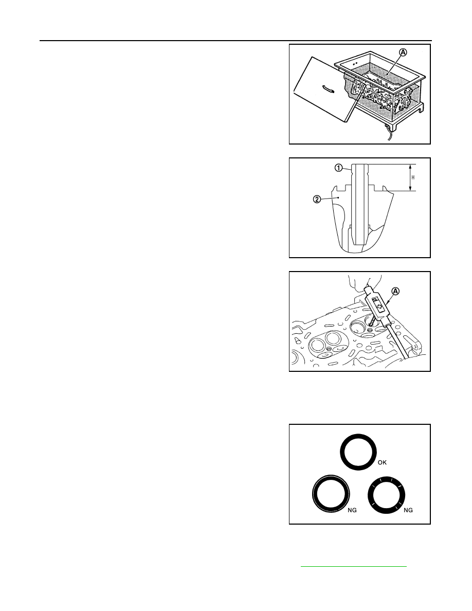
4.
Heat cylinder head to 110
°
to 130
°
C (230
°
to 266
°
F) by soaking
in heated oil (A).
5.
Press valve guide (1) from camshaft side to dimensions as
shown.
CAUTION:
Cylinder head contains heat, when working, wear protective
equipment to avoid getting burned.
6.
Apply reamer finish to valve guide using suitable tool (A).
VALVE SEAT CONTACT
• After confirming that the dimensions of valve guides and valves are within specifications, perform this proce-
dure.
• Apply prussian blue (or white lead) onto contacting surface of valve seat to check the condition of the valve
contact on the surface.
• Check if the contact area band is continuous all around the circum-
ference.
• If not, grind to adjust valve fitting and check again. If the contacting
surface still has NG conditions even after the re-check, replace
valve seat.
VALVE SEAT REPLACEMENT
When valve seat is removed, replace with oversized [0.5 mm (0.020 in)] valve seat.
1.
Bore out old seat until it collapses. Boring should not continue beyond the bottom face of the seat recess
in cylinder head. Set the machine depth stop to ensure this. Refer to
.
PBIC3214J
2
: Cylinder head
Projection “H”
: 13.35 - 13.65 mm (0.526 - 0.537 in)
PBIC3217J
Standard
: 5.500 - 5.518 mm (0.2165 - 0.2172 in)
PBIC3215J
SBIA0322E