Nissan Tiida C11. Manual - part 695


  Главная      Nissan     Nissan Tiida C11 - Service Manual


поиск по сайту            


содержание   ..  693  694  695  696   ..


Nissan Tiida C11. Manual - part 695


EM-132

< SYMPTOM DIAGNOSIS >

[MR18DE]

NOISE, VIBRATION AND HARSHNESS (NVH) TROUBLESHOOTING

SYMPTOM DIAGNOSIS

NOISE, VIBRATION AND HARSHNESS (NVH) TROUBLESHOOTING

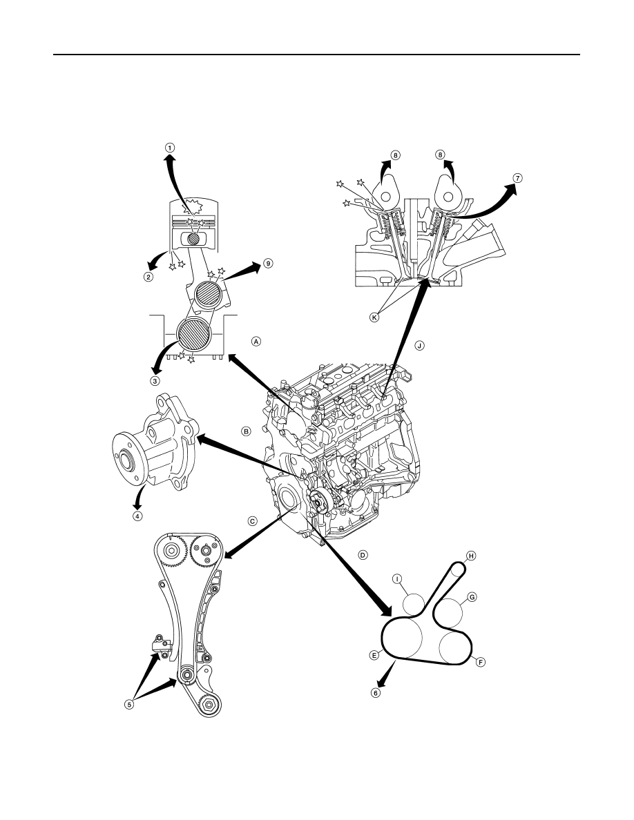
NVH Troubleshooting - Engine Noise

INFOID:0000000001337774

WBIA0769E

1.

Piston pin noise

2.

Piston slap noise

3.

Main bearing noise

4.

Water pump noise

5.

Timing chain and tensioner noise

6.

Drive belt noise (stick/slipping)

7.

Tappet noise

8.

Camshaft bearing noise

9.

Connecting rod noise

NOISE, VIBRATION AND HARSHNESS (NVH) TROUBLESHOOTING

EM-133

< SYMPTOM DIAGNOSIS >

[MR18DE]

C

D

E

F

G

H

I

J

K

L

M

A

EM

N

P

O

Use the Chart Below to Help You Find the Cause of the Symptom

INFOID:0000000001337775

1.

Locate the area where noise occurs.

2.

Confirm the type of noise.

3.

Specify the operating condition of engine.

4.

Check specified noise source.

If necessary, repair or replace these parts.

A: Closely related

B: Related

C: Sometimes related

—: Not related

A.

Rotational mechanism

B.

Water pump

C.

Timing chain

D.

Drive belt

E.

Crankshaft pulley

F.

A/C compressor

G.

Water pump

H.

Generator

I.

Tension pulley

J.

Valve mechanism

K.

Valves

Location 

of noise

Type of 

noise

Operating condition of engine

Source of 

noise

Check item

Refer-

ence page

Before 

warm-

up

After 

warm-

up

When 

start-

ing

When 

idling

When 

racing

While 

driving

Top of en-
gine
Rocker 
cover
Cylinder 
head

Ticking or 
clicking

C

A

A

B

Tappet 
noise

Valve clearance

EM-238

Rattle

C

A

A

B

C

Camshaft 
bearing 
noise

Camshaft journal oil 
clearance
Camshaft runout

EM-186
EM-186

Crank-
shaft pul-
ley
Cylinder 
block 
(Side of 
engine)
Oil pan

Slap or 
knock

A

B

B

Piston pin 
noise

Piston to piston pin oil 
clearance
Connecting rod bushing 
oil clearance

EM-219
EM-219

Slap or 
rap

A

B

B

A

Piston 
slap noise

Piston to cylinder bore 
clearance
Piston ring side clear-
ance
Piston ring end gap
Connecting rod bend 
and torsion

EM-219
EM-219
EM-219
EM-219

Knock

A

B

C

B

B

B

Connect-
ing rod 
bearing 
noise

Connecting rod bushing 
oil clearance 
Connecting rod bearing 
oil clearance

EM-219
EM-219

Knock

A

B

A

B

C

Main bear-
ing noise

Main bearing oil clear-
ance
Crankshaft runout

EM-219
EM-219

Front of 
engine
Front cov-
er

Tapping or 
ticking

A

A

B

B

B

Timing 
chain and 
chain ten-
sioner 
noise

Timing chain cracks 
and wear
Timing chain tensioner 
operation

EM-177

Front of 
engine

Squeak-
ing or fizz-
ing

A

B

B

C

Drive belt 
(Sticking 
or slip-
ping)

Drive belt deflection

EM-142

Creaking

A

B

A

B

A

B

Drive belt 
(Slipping)

Idler pulley bearing op-
eration

Squall
Creak

A

B

B

A

B

Water 
pump 
noise

Water pump operation

CO-44

EM-134

< PRECAUTION >

[MR18DE]

PRECAUTIONS

PRECAUTION

PRECAUTIONS

Precaution for Supplemental Restraint System (SRS) "AIR BAG" and "SEAT BELT 
PRE-TENSIONER"

INFOID:0000000001527643

The Supplemental Restraint System such as “AIR BAG” and “SEAT BELT PRE-TENSIONER”, used along
with a front seat belt, helps to reduce the risk or severity of injury to the driver and front passenger for certain
types of collision. Information necessary to service the system safely is included in the SR and SB section of
this Service Manual.

WARNING:

• To avoid rendering the SRS inoperative, which could increase the risk of personal injury or death in

the event of a collision which would result in air bag inflation, all maintenance must be performed by
an authorized NISSAN/INFINITI dealer.

• Improper maintenance, including incorrect removal and installation of the SRS, can lead to personal

injury caused by unintentional activation of the system. For removal of Spiral Cable and Air Bag
Module, see the SR section.

• Do not use electrical test equipment on any circuit related to the SRS unless instructed to in this

Service Manual. SRS wiring harnesses can be identified by yellow and/or orange harnesses or har-
ness connectors.

Precaution for Procedure without Cowl Top Cover

INFOID:0000000001337763

When performing the procedure after removing cowl top cover, cover
the lower end of windshield.

Precaution Necessary for Steering Wheel Rotation After Battery Disconnect

INFOID:0000000001337764

NOTE:
• This Procedure is applied only to models with Intelligent Key system and NATS (NISSAN ANTI-THEFT SYS-

TEM).

• Remove and install all control units after disconnecting both battery cables with the ignition knob in the

LOCK

 position.

• Always use CONSULT-II to perform self-diagnosis as a part of each function inspection after finishing work.

If DTC is detected, perform trouble diagnosis according to self-diagnostic results.

For models equipped with the Intelligent Key system and NATS, an electrically controlled steering lock mech-
anism is adopted on the key cylinder.
For this reason, if the battery is disconnected or if the battery is discharged, the steering wheel will lock and
steering wheel rotation will become impossible.
If steering wheel rotation is required when battery power is interrupted, follow the procedure below before
starting the repair operation.

OPERATION PROCEDURE

1.

Connect both battery cables.
NOTE:
Supply power using jumper cables if battery is discharged.

2.

Use the Intelligent Key or mechanical key to turn the ignition switch to the 

ACC

 position. At this time, the

steering lock will be released.

PIIB3706J

PRECAUTIONS

EM-135

< PRECAUTION >

[MR18DE]

C

D

E

F

G

H

I

J

K

L

M

A

EM

N

P

O

3.

Disconnect both battery cables. The steering lock will remain released and the steering wheel can be
rotated.

4.

Perform the necessary repair operation.

5.

When the repair work is completed, return the ignition switch to the 

LOCK

 position before connecting

the battery cables. (At this time, the steering lock mechanism will engage.)

6.

Perform a self-diagnosis check of all control units using CONSULT-II. 

Precaution for Drain Coolant

INFOID:0000000001337765

• Drain coolant when engine is cooled.

Precaution for Disconnecting Fuel Piping

INFOID:0000000001337766

• Before starting work, make sure no fire or spark producing items are in the work area. 
• Release fuel pressure before disassembly.
• After disconnecting pipes, plug openings to stop fuel leakage.

Precaution for Removal and Disassembly

INFOID:0000000001337767

• When instructed to use special service tools, use the specified tools. Always be careful to work safely, avoid

forceful or uninstructed operations. 

• Exercise maximum care to avoid damage to mating or sliding surfaces.
• Cover openings of engine system with tape or the equivalent, if necessary, to seal out foreign materials.
• Mark and arrange disassembly parts in an organized way for easy troubleshooting and assembly.
• When loosening nuts and bolts, as a basic rule, start with the one furthest outside, then the one diagonally

opposite, and so on. If the order of loosening is specified, do exactly as specified. Power tools may be used
where noted in the step.

Precaution for Inspection, Repair and Replacement

INFOID:0000000001337768

• Before repairing or replacing, thoroughly inspect parts. Inspect new replacement parts in the same way, and

replace if necessary.

Precaution for Assembly and Installation

INFOID:0000000001337769

• Use torque wrench to tighten bolts or nuts to specification.
• When tightening nuts and bolts, as a basic rule, equally tighten in several different steps starting with the

ones in center, then ones on inside and outside diagonally in this order. If the order of tightening is specified,
do exactly as specified.

• Replace with new gasket, packing, oil seal or O-ring.
• Thoroughly wash, clean, and air-blow each part. Carefully check oil or coolant passages for any restriction

and blockage. 

• Avoid damaging sliding or mating surfaces. Completely remove foreign materials such as cloth lint or dust.

Before assembly, oil sliding surfaces well. 

• Release air within route after draining coolant. 
• Before starting engine, apply fuel pressure to fuel lines with turning ignition switch ON (with engine stopped).

Then make sure that there are no leaks at fuel line connections.

• After repairing, start engine and increase engine speed to check coolant, fuel, oil, and exhaust systems for

leakage.

Parts Requiring Angular Tightening

INFOID:0000000001337770

• Use an angle wrench for the final tightening of the following engine parts: 
- Cylinder head bolts
- Camshaft sprocket (INT)
- Main bearing cap bolts
- Connecting rod cap nuts
- Crankshaft pulley bolt (No angle wrench is required as the bolt flange is provided with notches for angular

tightening)

• Do not use a torque value for final tightening. 

Tool number

: KV10112100 (BT-8653-A)


содержание   ..  693  694  695  696   ..