содержание .. 540 541 542 543 ..
Nissan Tiida C11. Manual - part 542
EC-818
< COMPONENT DIAGNOSIS >
[MR18DE]
P0133 HO2S1
If DTC Confirmation Procedure has been previously conducted, always turn ignition switch OFF and wait at
least 10 seconds before conducting the next test.
TESTING CONDITION:
Always perform at a temperature above -10
°
C (14
°
F).
Before performing the following procedure, confirm that battery voltage is more than 11V at idle.
Do you have CONSULT-III?
YES
>> GO TO 2.
NO
>> GO TO 3.
2.
PERFORM DTC CONFIRMATION PROCEDURE-I
With CONSULT-III
1.
Start engine and warm it up to normal operating temperature.
2.
Stop engine and wait at least 10 seconds.
3.
Turn ignition switch ON and select “HO2S1 (B1) P0133” of “HO2S1” in “DTC WORK SUPPORT” mode
with CONSULT-III.
4.
Touch “START”.
5.
Start engine and let it idle for at least 3 minutes.
NOTE:
Never raise engine speed above 3,600 rpm after this step. If the engine speed limit is exceeded,
return to step 5.
6.
When the following conditions are met, “TESTING” will be displayed on the CONSULT-III screen. Maintain
the conditions continuously until “TESTING” changes to “COMPLETED”. (It will take approximately 40 to
50 seconds.)
CAUTION:
Always drive vehicle at a safe speed.
If “TESTING” is not displayed after 5 minutes, retry from step 2.
7.
Touch “SELF-DIAG RESULTS”.
Which displayed on COUSULT-III screen?
OK
>> INSPECTION END.
NG
>> Go to
3.
PERFORM COMPONENT FUNCTION CHECK
Without CONSULT-III
1.
Start engine and warm it up to normal operating temperature.
2.
Set volmeter probes between ECM harness connector terminals as follows.
Is the inspection result normal?
YES
>> INSPECTION END.
NO
>> Go to
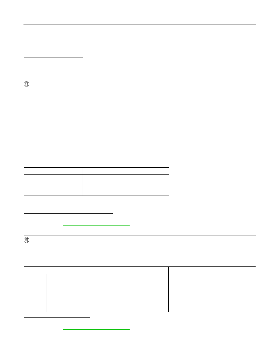
ENG SPEED
1,300 - 3,500 rpm
VHCL SPEED SE
More than 80 km/h (50 MPH)
B/FUEL SCHDL
3 - 15 msec
Shift lever
Suitable position
(+)
(–)
Condition
Voltage
Connector
Terminal
Connector
Terminal
F11
49
(HO2S1 signal)
F11
56
Engine speed held at
2,000 rpm constant un-
der no load.
• The voltage fluctuates between 0 to 0.3V and
0.6 to 1.0V more than 5 times within 10 sec-
onds.
1 time: 0 - 0.3V
→
0.6 - 1.0V
→
0 - 0.3V
2 times: 0 - 0.3V
→
0.6 - 1.0V
→
0 - 0.3V
→
0.6
- 1.0V
→
0 - 0.3V