содержание .. 523 524 525 526 ..
Nissan Tiida C11. Manual - part 525
EC-750
< FUNCTION DIAGNOSIS >
[MR18DE]
EVAPORATIVE EMISSION SYSTEM
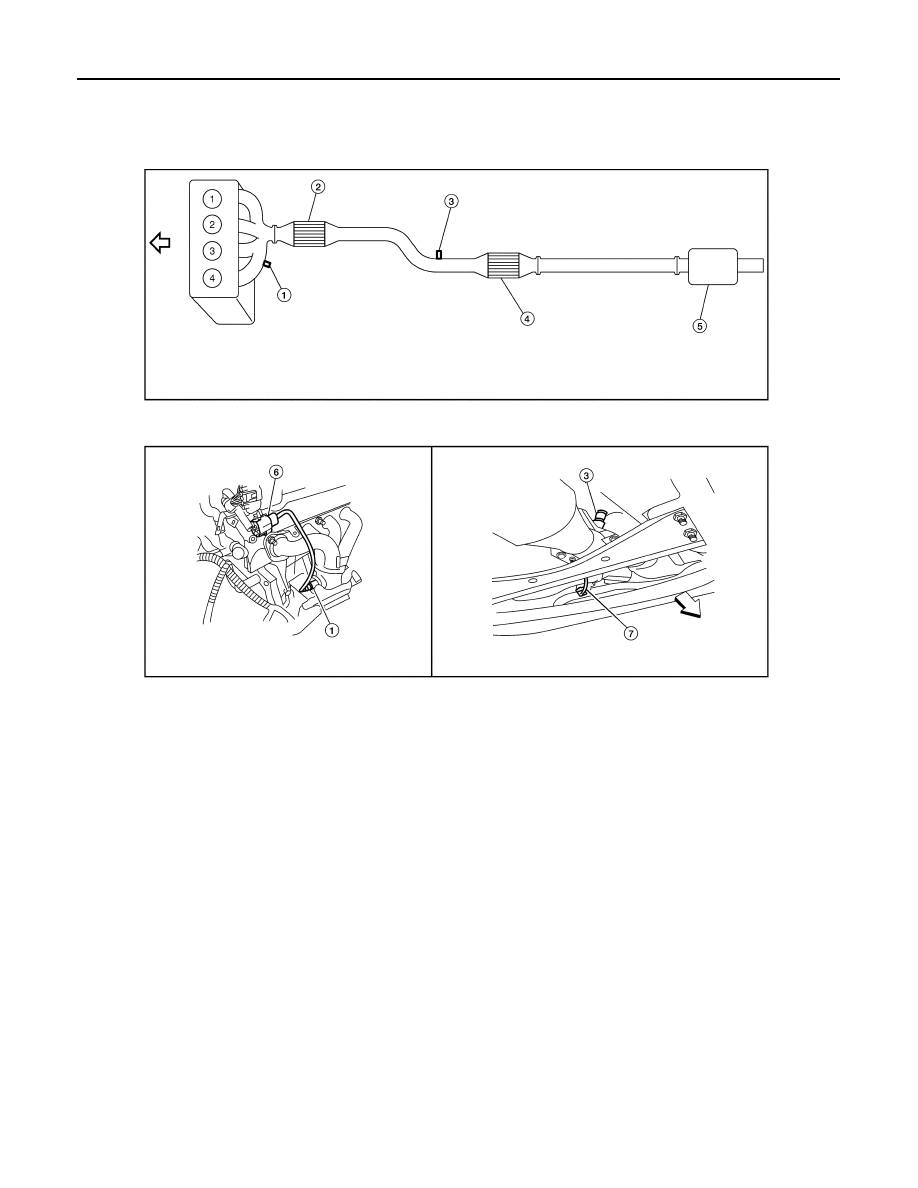
1.
Heated oxygen sensor 1
2.
Three way catalyst (Manifold)
3.
Heated oxygen sensor 2
4.
Three way catalyst (Under floor)
5.
Muffler
6.
Heated oxygen sensor 1 harness
connector
7.
Heated oxygen sensor 2 harness
connector
BBIA0733E