Nissan Tiida C11. Manual - part 369


  Главная      Nissan     Nissan Tiida C11 - Service Manual


поиск по сайту            


содержание   ..  367  368  369  370   ..


Nissan Tiida C11. Manual - part 369


EC-126

< COMPONENT DIAGNOSIS >

[HR16DE (WITH EURO-OBD)]

POWER SUPPLY AND GROUND CIRCUIT

NO

>> Repair open circuit or short to power in harness or connectors.

11.

CHECK ECM POWER SUPPLY CIRCUIT-VI

1.

Disconnect ECM harness connector.

2.

Disconnect IPDM E/R harness connector .

3.

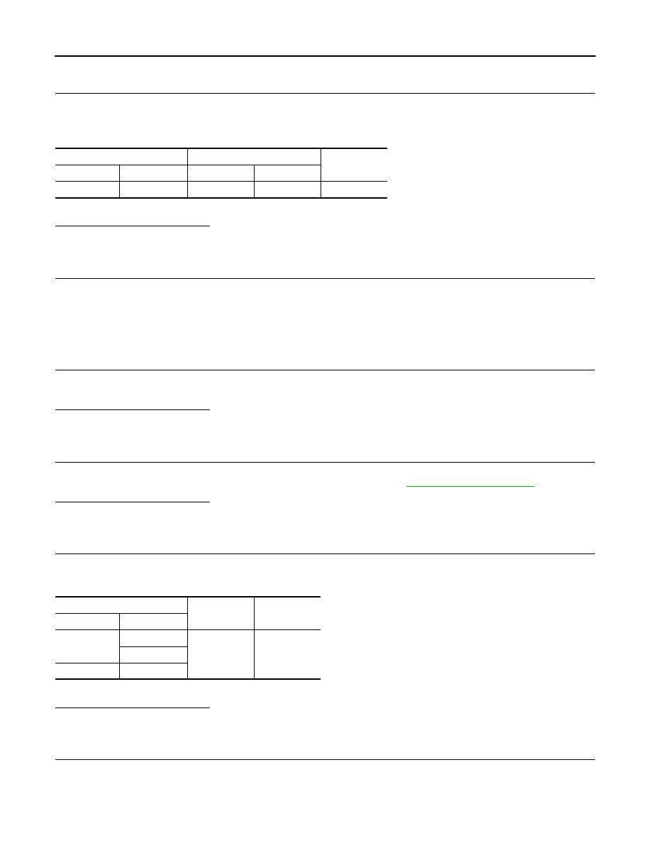
Check the continuity between ECM harness connector and IPDM E/R harness connector.

4.

Also check harness for short to ground and short to power.

Is the inspection result normal?

YES

>> GO TO 13.

NO

>> GO TO 12.

12.

DETECT MALFUNCTIONING PART

Check the following.
• Junction block connectors E8, F8
• Harness for open or short between ECM and IPDM E/R

>> Repair open circuit or short to ground or short to power in harness or connectors.

13.

CHECK 20A FUSE

1.

Disconnect 20A fuse (No. 53) from IPDM E/R.

2.

Check 20A fuse.

Is the inspection result normal?

YES

>> GO TO 17.

NO

>> Replace 20A fuse.

14.

CHECK GROUND CONNECTION-II

1.

Turn ignition switch OFF.

2.

Check ground connection E15, E24. Refer to Ground Inspection in 

GI-58, "Circuit Inspection"

.

Is the inspection result normal?

YES

>> GO TO 15.

NO

>> Repair or replace ground connection.

15.

CHECK ECM GROUND CIRCUIT FOR OPEN AND SHORT-II

1.

Disconnect ECM harness connector.

2.

Check the continuity between ECM harness connector and ground.

3.

Also check harness for short to power.

Is the inspection result normal?

YES

>> GO TO 17.

NO

>> GO TO 16.

16.

DETECT MALFUNCTIONING PART

Check the following.
• Harness or connectors F8, E8
• Harness for open or short between ECM and ground

ECM

IPDM E/R

Continuity

Connector

Terminal

Connector

Terminal

F10

32

E43

7

Existed

ECM

Ground

Continuity

Connector

Terminal

F10

10

Ground

Existed

11

E16

108

POWER SUPPLY AND GROUND CIRCUIT

EC-127

< COMPONENT DIAGNOSIS >

[HR16DE (WITH EURO-OBD)]

C

D

E

F

G

H

I

J

K

L

M

A

EC

N

P

O

>> Repair open circuit or short to power in harness or connectors.

17.

CHECK INTERMITTENT INCIDENT

Refer to 

GI-55, "Intermittent Incident"

.

Is the inspection result normal?

YES

>> Replace IPDM E/R.

NO

>> Repair open circuit or short to power in harness or connectors.

EC-128

< COMPONENT DIAGNOSIS >

[HR16DE (WITH EURO-OBD)]

U1000, U1001 CAN COMM CIRCUIT

U1000, U1001 CAN COMM CIRCUIT

Description

INFOID:0000000001670890

CAN (Controller Area Network) is a serial communication line for real time application. It is an on-vehicle mul-
tiplex communication line with high data communication speed and excellent error detection ability. Many elec-
tronic control units are equipped onto a vehicle, and each control unit shares information and links with other
control units during operation (not independent). In CAN communication, control units are connected with 2
communication lines (CAN H line, CAN L line) allowing a high rate of information transmission with less wiring.
Each control unit transmits/receives data but selectively reads required data only.

DTC Logic

INFOID:0000000001670891

DTC DETECTION LOGIC

DTC CONFIRMATION PROCEDURE

1.

PERFORM DTC CONFIRMATION PROCEDURE

1.

Turn ignition switch ON and wait at least 3 seconds.

2.

Check 1st trip DTC.

Is 1st trip DTC detected?

YES

>>

EC-128, "Diagnosis Procedure"

.

NO

>> INSPECTION END

Diagnosis Procedure

INFOID:0000000001670892

Go to 

LAN-22, "Trouble Diagnosis Flow Chart"

.

DTC No.

Trouble diagnosis 

name

DTC detecting condition

Possible cause

U1000

CAN communication 
line

When ECM is not transmitting or receiving CAN com-
munication signal of OBD (emission related diagno-
sis) for 2 seconds or more.

• Harness or connectors

(CAN communication line is open or 
shorted)

U1001

When ECM is not transmitting or receiving CAN com-
munication signal other than OBD (emission related 
diagnosis) for 2 seconds or more.

U1010 CONTROL UNIT (CAN)

EC-129

< COMPONENT DIAGNOSIS >

[HR16DE (WITH EURO-OBD)]

C

D

E

F

G

H

I

J

K

L

M

A

EC

N

P

O

U1010 CONTROL UNIT (CAN)

Description

INFOID:0000000001670893

CAN (Controller Area Network) is a serial communication line for real time application. It is an on-vehicle mul-
tiplex communication line with high data communication speed and excellent error detection ability. Many elec-
tronic control units are equipped onto a vehicle, and each control unit shares information and links with other
control units during operation (not independent). In CAN communication, control units are connected with 2
communication lines (CAN H line, CAN L line) allowing a high rate of information transmission with less wiring.
Each control unit transmits/receives data but selectively reads required data only.

DTC Logic

INFOID:0000000001670894

DTC DETECTION LOGIC

DTC CONFIRMATION PROCEDURE

1.

PERFORM DTC CONFIRMATION PROCEDURE

1.

Turn ignition switch ON.

2.

Check DTC.

Is DTC detected?

YES

>> Go to 

EC-129, "Diagnosis Procedure"

.

NO

>> INSPECTION END

Diagnosis Procedure

INFOID:0000000001670895

1.

INSPECTION START

With CONSULT-III

1.

Turn ignition switch ON.

2.

Select “SELF-DIAG RESULTS” mode with CONSULT-III.

3.

Touch “ERASE”.

4.

Perform DTC CONFIRMATION PROCEDURE.
See 

EC-129, "DTC Logic"

.

5.

Check DTC.

With GST

1.

Turn ignition switch ON.

2.

Select “Service $04” with GST.

3.

Perform DTC CONFIRMATION PROCEDURE.
See 

EC-129, "DTC Logic"

.

4.

Check DTC.

Is the DTC U1010 displayed again?

YES

>> GO TO 2.

NO

>> INSPECTION END

2.

REPLACE ECM

1.

Replace ECM.

2.

Go to 

EC-25, "ADDITIONAL SERVICE WHEN REPLACING CONTROL UNIT : Special Repair Require-

ment"

.

>> INSPECTION END

DTC No.

Trouble diagnosis name

DTC detecting condition

Possible cause

U1010

CAN communication bus

When detecting error during the initial diagno-
sis of CAN controller of ECM.

• ECM


содержание   ..  367  368  369  370   ..