Nissan Tiida C11. Manual - part 349


  Главная      Nissan     Nissan Tiida C11 - Service Manual


поиск по сайту            


содержание   ..  347  348  349  350   ..


Nissan Tiida C11. Manual - part 349


EC-46

< FUNCTION DIAGNOSIS >

[HR16DE (WITH EURO-OBD)]

MULTIPORT FUEL INJECTION SYSTEM

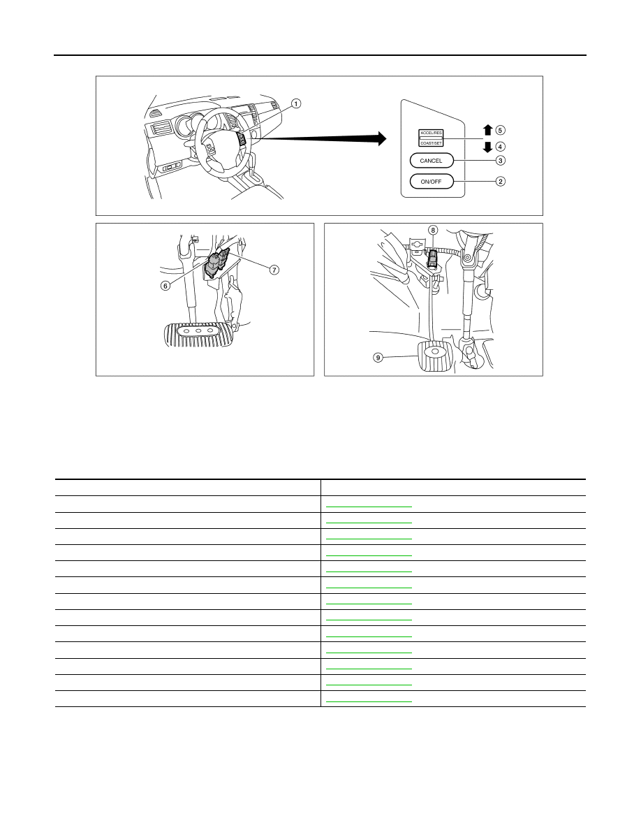
Component Description

INFOID:0000000001161145

1.

ASCD steering switch

2.

MAIN switch

3.

CANCEL switch

4.

SET/COAST switch

5.

RESUME/ACCELERATE switch

6.

ASCD brake switch

7.

Stop lamp switch

8.

ASCD clutch switch

9.

Clutch pedal

ALBIA0273ZZ

Component

Reference

Accelerator pedal position sensor

EC-286, "Description"

Camshaft position sensor (PHASE)

EC-201, "Description"

Crankshaft position sensor (POS)

EC-197, "Description"

Engine coolant temperature sensor

EC-142, "Description"

Fuel injector

EC-313, "Description"

Heated oxygen sensor 1

EC-148, "Description"

Heated oxygen sensor 2

EC-166, "Description"

Intake air temperature sensor

EC-139, "Description"

Knock sensor

EC-195, "Description"

Mass air flow sensor

EC-134, "Description"

Park/neutral position (PNP) switch

EC-280, "Description"

Throttle position sensor

EC-261, "Description"

Vehicle speed sensor

EC-213, "Description"

ELECTRIC IGNITION SYSTEM

EC-47

< FUNCTION DIAGNOSIS >

[HR16DE (WITH EURO-OBD)]

C

D

E

F

G

H

I

J

K

L

M

A

EC

N

P

O

ELECTRIC IGNITION SYSTEM

System Diagram

INFOID:0000000001161146

System Description

INFOID:0000000001161147

INPUT/OUTPUT SIGNAL CHART

*1: This signal is sent to the ECM through CAN communication line.

*2: ECM determines the start signal status by the signals of engine speed and battery voltage.

SYSTEM DESCRIPTION

Firing order: 1 - 3 - 4 - 2 
The ignition timing is controlled by the ECM to maintain the best air-fuel ratio for every running condition of the
engine. The ignition timing data is stored in the ECM.
The ECM receives information such as the injection pulse width and camshaft position sensor (PHASE) sig-
nal. Computing this information, ignition signals are transmitted to the power transistor.
During the following conditions, the ignition timing is revised by the ECM according to the other data stored in
the ECM.
• At starting
• During warm-up
• At  idle
• At low battery voltage
• During acceleration
The knock sensor retard system is designed only for emergencies. The basic ignition timing is programmed
within the anti-knocking zone, if recommended fuel is used under dry conditions. The retard system does not

JMBIA0174GB

Sensor

Input Signal to ECM

ECM function

Actuator

Crankshaft position sensor (POS)

Engine speed*

2

Piston position

Ignition timing 
control

Ignition coil (with power transis-
tor)

Camshaft position sensor (PHASE)

Mass air flow sensor

Amount of intake air

Engine coolant temperature sensor

Engine coolant temperature

Throttle position sensor

Throttle position

Accelerator pedal position sensor

Accelerator pedal position

Battery

Battery voltage*

2

Knock sensor

Engine knocking

Park/neutral position (PNP) switch

Gear position

Combination meter*

1

Vehicle speed

EC-48

< FUNCTION DIAGNOSIS >

[HR16DE (WITH EURO-OBD)]

ELECTRIC IGNITION SYSTEM

operate under normal driving conditions. If engine knocking occurs, the knock sensor monitors the condition.
The signal is transmitted to the ECM. The ECM retards the ignition timing to eliminate the knocking condition.

Component Parts Location

INFOID:0000000001677953

1.

Ignition coil (with power transistor) 
and spark plug

2.

Intake valve timing control solenoid 
valve

3.

Refrigerant pressure sensor

4.

Knock sensor

5.

Fuel injector

6.

Cooling fan motor

7.

Camshaft position sensor (PHASE)

8.

IPDM E/R

9.

ECM

10. Mass air flow sensor (with intake air 

temperature sensor)

11.

Engine coolant temperature sensor

12. Electric throttle control actuator

(with built in throttle position sensor 
and throttle control motor)

13. EVAP canister purge volume control 

solenoid valve

PBIB2939E

ELECTRIC IGNITION SYSTEM

EC-49

< FUNCTION DIAGNOSIS >

[HR16DE (WITH EURO-OBD)]

C

D

E

F

G

H

I

J

K

L

M

A

EC

N

P

O

1.

Mass air flow sensor
(with intake air temperature sensor)

2.

Engine coolant temperature sensor

3.

Electric throttle control actuator

4.

Camshaft position sensor (PHASE)

5.

Ignition coil (with power transistor)

6.

Fuel injector

7.

EVAP canister purge volume control 
solenoid valve

Vehicle front

PBIB2940E


содержание   ..  347  348  349  350   ..