Nissan Tiida C11. Manual - part 1424


  Главная      Nissan     Nissan Tiida C11 - Service Manual


поиск по сайту            


содержание   ..  1422  1423  1424  1425   ..


Nissan Tiida C11. Manual - part 1424


VTL-32

< FUNCTION DIAGNOSIS >

[MANUAL AIR CONDITIONER]

AIR CONDITIONER FILTER

FUNCTION DIAGNOSIS

AIR CONDITIONER FILTER

Description

INFOID:0000000001710935
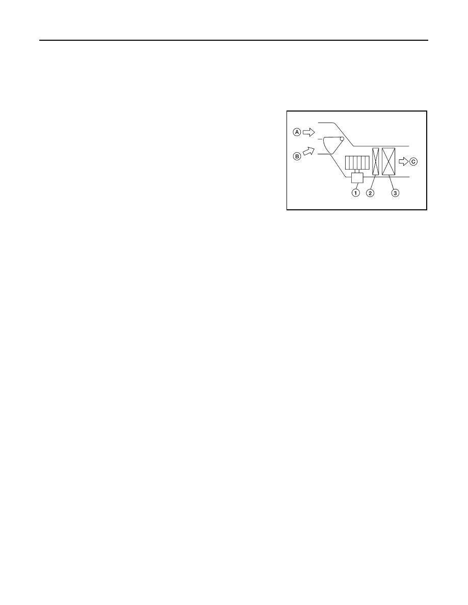
FUNCTION

The fresh air (A) and the recirculated air (B) drawn inside the pas-
senger compartment by the front blower motor (1) is kept clean (C)
on either mode by the air conditioner filter (2), located before the
evaporator (3), in the A/C unit assembly.

WJIA2253E

AIR CONDITIONER FILTER

VTL-33

< ON-VEHICLE MAINTENANCE >

[MANUAL AIR CONDITIONER]

C

D

E

F

G

H

J

K

L

M

A

B

VTL

N

O

P

ON-VEHICLE MAINTENANCE

AIR CONDITIONER FILTER

Removal and Installation

INFOID:0000000001710936

REPLACEMENT TIMING

Replace the air conditioner filter according to the maintenance schedules. Refer to 

MA-7, "Periodic Mainte-

nance"

.

NOTE:
The air conditioner filter caution label is located inside the glove box door.

REPLACEMENT PROCEDURES

1.

Remove the instrument lower finisher and instrument lower cover (LH) for LHD only. Refer to 

IP-11,

"Removal and Installation"

.

2.

Remove the glove box assembly and instrument lower cover (RH) for RHD only. Refer to 

IP-11, "Removal

and Installation"

.

3.

Compress the air conditioner filter (1) downward while sliding it
to the RH side of the vehicle to release the upper pawl.

4.

Move the bottom of air conditioner filter (1) upward as shown to
release the bottom tab, then remove it.

5.

Replace the air conditioner filter with new one and install the new filter in the A/C unit assembly. 

CAUTION:

Make sure that the air conditioner filter lower tab is fully seated, and that the air conditioner upper
pawl is locked into place securing the new filter into the A/C unit assembly.

6.

Install the glove box assembly and instrument lower cover (RH) for RHD only. Refer to 

IP-11, "Removal

and Installation"

.

7.

Install the instrument lower finisher and instrument lower cover (LH) for LHD only. Refer to 

IP-11,

"Removal and Installation"

.

SJIA0652E

VTL-34

< ON-VEHICLE REPAIR >

[MANUAL AIR CONDITIONER]

CONTROLLER

ON-VEHICLE REPAIR

CONTROLLER

Removal and Installation

INFOID:0000000001696528

REMOVAL

1.

Remove cluster lid C and instrument finisher D. Refer to 

IP-11, "Removal and Installation"

.

2.

Remove intake door lever knob. Refer to 

VTL-35, "Disassembly

and Assembly"

.

3.

Remove mounting screws and clips, and then remove controller
finisher.

4.

Remove mounting screws, and then pull out controller.

5.

Remove instrument panel and pad. Refer to 

IP-11, "Removal and Installation"

.

6.

Remove air mix door cable, mode door cable and intake door cable from A/C unit assembly.

7.

Disconnect connector, and then remove controller.

INSTALLATION

Installation is in the reverse order of removal.

CAUTION:

Adjust the door cables during installation. Refer to 

VTL-45, "Intake Door Cable Adjustment"

VTL-47,

"Mode Door Cable Adjustment"

  and 

VTL-46, "Air Mix Door Cable Adjustment"

.

ZJIA0697E

ZJIA0698E

CONTROLLER

VTL-35

< ON-VEHICLE REPAIR >

[MANUAL AIR CONDITIONER]

C

D

E

F

G

H

J

K

L

M

A

B

VTL

N

O

P

Disassembly and Assembly

INFOID:0000000001696529

CAUTION:

Install inner cable of each door cable to the corresponding
lever, as shown in the figure. Press outer cable until it hooks on
the tabs and becomes secure.

1.

Air mix door cable

2.

Intake door cable

3.

Mode door cable

4.

A/C controller assembly

5.

Mode control dial

6.

Rear DEF button

7.

A/C button

8.

Temperature control dial

9.

Illumination bulb

10. Intake door lever knob

11.

Fan control dial

ZJIA0106J

MJIA0038E


содержание   ..  1422  1423  1424  1425   ..