Nissan Tiida C11. Manual - part 1227


  Главная      Nissan     Nissan Tiida C11 - Service Manual


поиск по сайту            


содержание   ..  1225  1226  1227  1228   ..


Nissan Tiida C11. Manual - part 1227


EPS WARNING LAMP DOES NOT TURN OFF

STC-31

< SYMPTOM DIAGNOSIS >

[EPS]

C

D

E

F

H

I

J

K

L

M

A

B

STC

N

O

P

EPS WARNING LAMP DOES NOT TURN OFF 

Diagnosis Procedure

INFOID:0000000001697734

SYMPTOM:

EPS warning lamp does not turn OFF for several seconds after starting the engine.

DIAGNOSTIC PROCEDURE

1.

CHECK SELF-DIAGNOSTIC RESULTS

Perform self-diagnosis. Refer to 

STC-7, "CONSULT-III Function (EPS)"

.

Is any malfunction detected by self-diagnosis?

YES

>> Check the malfunctioning system.

NO

>> GO TO 2.

2.

CHECK EPS CONTROL UNIT POWER SUPPLY CIRCUIT

1.

Turn ignition switch OFF.

2.

Disconnect EPS control unit harness connector.

3.

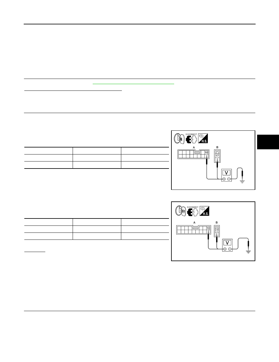
Turn ignition switch ON. (Do not start engine.)

4.

Check voltage between EPS control unit harness connector
M53 (A) terminal 10 and M54 (B) terminal 17 and ground.

5.

Turn ignition switch OFF.

6.

Check voltage between EPS control unit harness connector
M53 (A) terminal 10 and M54 (B) terminal 17 and ground.

7.

Connect EPS control unit harness connector.

OK or NG

OK

>> GO TO 3.

NG

>>

Check the following. If any items are damaged, repair
or replace damaged parts.

• 60 A fusible link (letter m , located in the fuse and fusible link box).
• 10 A fuse [No. 2, located in the fuse block (J/B)].
• Harness for short or open between battery and EPS control unit harness connector M54 termi-

nal 17.

• Harness for short or open between ignition switch and EPS control unit harness connector M53

terminal 10.

3.

CHECK EPS CONTROL UNIT GROUND CIRCUIT

1.

Turn ignition switch OFF.

2.

Disconnect EPS control unit harness connector.

Connector

Terminal

Voltage

(A) M53

10 – Ground

Battery voltage

(B) M54

17 – Ground

Battery voltage

AWGIA0031ZZ

Connector

Terminal

Voltage

(A) M53

10 – Ground

Approx. 0 V

(B) M54

17 – Ground

Battery voltage

AWGIA0028ZZ

STC-32

< SYMPTOM DIAGNOSIS >

[EPS]

EPS WARNING LAMP DOES NOT TURN OFF

3.

Check continuity between EPS control unit harness connector
M54 terminal 18 and ground.

Also check harness for short to power.

4.

Connect EPS control unit harness connector.

OK or NG

OK

>> GO TO 4.

NG

>> Repair open circuit or short to ground or short to power

in harness or connectors.

4.

CHECK EPS CONTROL UNIT

Check EPS control unit input/output signal. Refer to 

STC-22, "EPS Control Unit Input/Output Signal Reference

Value"

.

OK or NG

OK

>> GO TO 5.

NG

>> Check EPS control unit pin terminals for damage or loose connection with harness connector. If

any items are damaged, repair or replace damaged parts.

5.

SYMPTOM CHECK

Check again.
OK or NG

OK

>> INSPECTION END

NG

>> Replace combination meter. Refer to 

MWI-94, "Removal and Installation"

.

Connector

Terminal

Continuity

M54

18

YES

AWGIA0029ZZ

STEERING WHEEL TURNING FORCE IS HEAVY OR LIGHT

STC-33

< SYMPTOM DIAGNOSIS >

[EPS]

C

D

E

F

H

I

J

K

L

M

A

B

STC

N

O

P

STEERING WHEEL TURNING FORCE IS HEAVY OR LIGHT

Diagnosis Procedure

INFOID:0000000001697735

SYMPTOM:

Steering wheel turning force is heavy or light, while driving.

DIAGNOSTIC PROCEDURE

1.

CHECK SYSTEM FOR CAN COMMUNICATION LINE

Perform self-diagnosis. Refer to 

STC-7, "CONSULT-III Function (EPS)"

.

Is the “CAN COMM CIRCUIT [U1000]” displayed?

YES

>> Perform trouble diagnosis for CAN communication line. Refer to 

STC-21, "Diagnosis Procedure"

.

NO

>> GO TO 2.

2.

CHECK VEHICLE SPEED SIGNAL

Perform self-diagnosis with ABS actuator and electric unit (control unit). Refer to 

BRC-25, "CONSULT-III

Function (ABS)"

 (with ABS) or 

BRC-105, "CONSULT-III Function (ABS)"

 (with ESP).

Is any malfunction detected by self-diagnosis?

YES

>> Check the malfunctioning system.

NO

>> GO TO 3.

3.

CHECK COMBINATION METER SIGNAL

Perform self-diagnosis with combination meter. Refer to 

MWI-22, "CONSULT-III Function (METER/M&A)"

.

Is any malfunction detected by self-diagnosis?

YES

>> Check the malfunctioning system.

NO

>> GO TO 4.

4.

CHECK ENGINE STATUS SIGNAL

Perform self-diagnosis for ECM. Refer to 

EC-107, "CONSULT-III Function"

 (HR16DE with EURO-OBD), 

EC-

462, "CONSULT-III Function"

 (HR16DE without EURO-OBD), 

EC-772, "CONSULT-III Function"

 (MR18DE),

EC-1104, "Diagnosis Description"

 (K9K).

Is any malfunction detected by self-diagnosis?

YES

>> Check the malfunctioning system.

NO

>> GO TO 5.

5.

CHECK EPS MOTOR SYSTEM

Perform trouble diagnosis for EPS motor. Refer to 

STC-13, "Diagnosis Procedure"

.

OK or NG

OK

>> GO TO 6.

NG

>> Repair or replace damaged parts.

6.

CHECK EPS CONTROL UNIT

Check EPS control unit input/output signal. Refer to 

STC-22, "EPS Control Unit Input/Output Signal Reference

Value"

.

OK or NG

OK

>> GO TO 7.

NG

>> Check EPS control unit pin terminals for damage or loose connection with harness connector. If

any items are damaged, repair or replace damaged parts.

7.

SYMPTOM CHECK

Check again.
OK or NG

OK

>> INSPECTION END

NG

>> Check the steering wheel turning force because there may be mechanical malfunction. Refer to

ST-6, "On-Vehicle Inspection and Service"

.

STC-34

< SYMPTOM DIAGNOSIS >

[EPS]

UNBALANCE STEERING WHEEL TURNING FORCE AND RETURN BETWEEN 

RIGHT AND LEFT

UNBALANCE STEERING WHEEL TURNING FORCE AND RETURN BE-
TWEEN RIGHT AND LEFT

Diagnosis Procedure

INFOID:0000000001697736

SYMPTOM:

Unbalance steering wheel turning force and return between right and left, while driving.

DIAGNOSTIC PROCEDURE

1.

CHECK EPS WARNING LAMP

Confirm EPS warning lamp during engine running.
Does EPS warning lamp turn OFF?

YES

>> GO TO 2.

NO

>> Go to 

STC-31, "Diagnosis Procedure"

.

2.

CHECK WHEEL ALIGNMENT

Check wheel alignment. Refer to 

FSU-6, "Wheel Alignment Inspection"

.

OK or NG

OK

>> GO TO 3.

NG

>> Adjust wheel alignment. Refer to 

FSU-6, "Wheel Alignment Inspection"

.

3.

CHECK EPS CONTROL UNIT

Check EPS control unit input/output signal. Refer to 

STC-22, "EPS Control Unit Input/Output Signal Reference

Value"

.

OK or NG

OK

>> GO TO 4.

NG

>> Check EPS control unit pin terminals for damage or loose connection with harness connector. If

any items are damaged, repair or replace damaged parts.

4.

SYMPTOM CHECK

Check again.
OK or NG

OK

>> INSPECTION END

NG

>> Check the steering wheel turning force because there may be mechanical malfunction. Refer to

ST-6, "On-Vehicle Inspection and Service"

.


содержание   ..  1225  1226  1227  1228   ..