содержание .. 110 111 112 113 ..
Nissan Tiida C11. Manual - part 112
CHG-26
< COMPONENT DIAGNOSIS >
[MR18DE]
S TERMINAL CIRCUIT
S TERMINAL CIRCUIT
Description
INFOID:0000000001724530
The output voltage of the generator is controlled by the IC regulator at terminal “3” (S) detecting the input volt-
age. Terminal “3” circuit detects the battery voltage to adjust the generator output voltage with the IC regulator.
Diagnosis Procedure
INFOID:0000000001724531
1.
CHECK VOLTAGE REGULATOR CIRCUIT CONNECTION
Check to see if connector F2 terminal 3 is clean and tight.
Is the inspection result normal?
YES
>> GO TO 2
NO
>> Repair terminal connection. Confirm repair by performing complete Starting/Charging system test.
Refer to Technical Service Bulletin.
2.
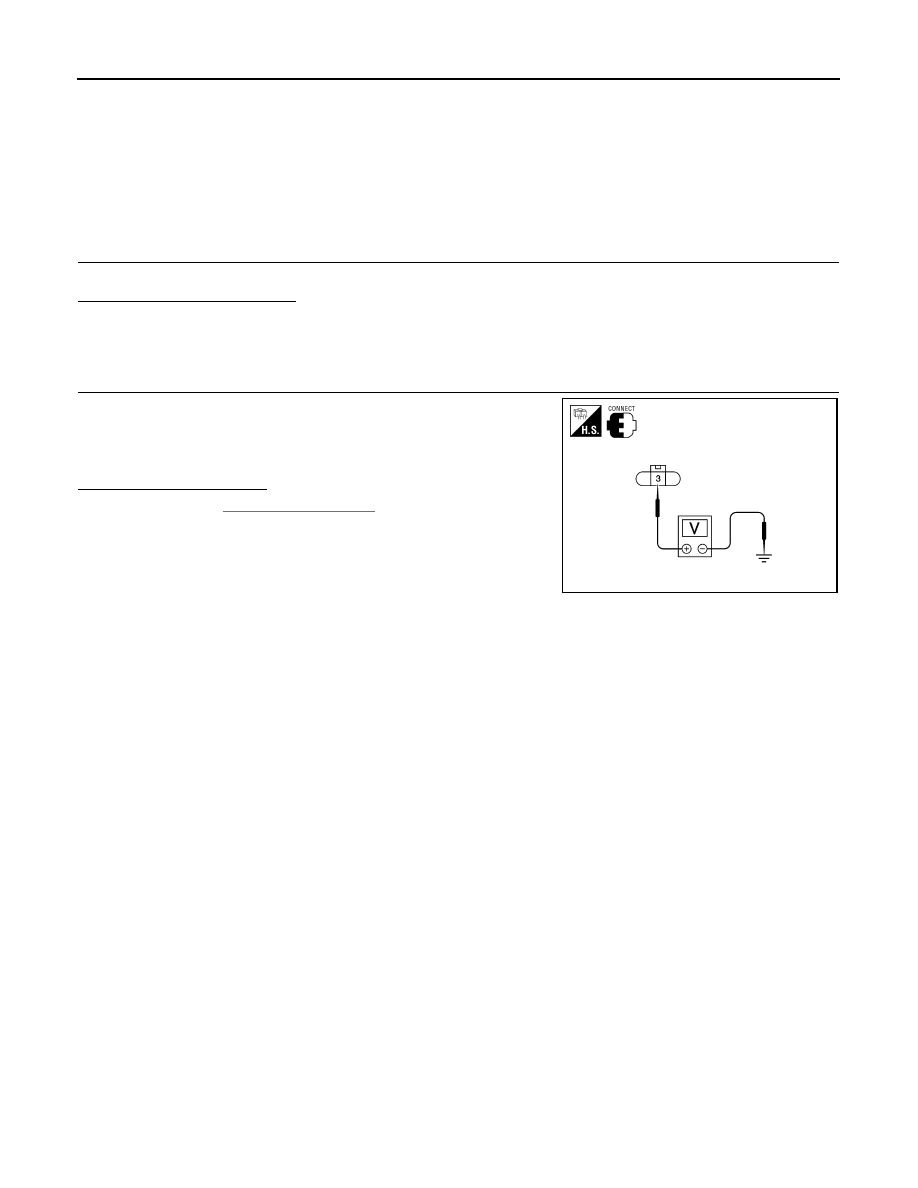
CHECK VOLTAGE REGULATOR CIRCUIT
Check voltage between generator harness connector F2 terminal 3
and ground.
Does battery voltage exist?
YES
>> Refer to
NO
>> Check harness for open between generator and fuse.
3 - ground
Battery voltage
ALMIA0201ZZ