содержание .. 1104 1105 1106 1107 ..
Nissan Tiida C11. Manual - part 1106
PCS
SIGNAL BUFFER SYSTEM
PCS-7
< FUNCTION DIAGNOSIS >
[IPDM E/R]
C
D
E
F
G
H
I
J
K
L
B
A
O
P
N
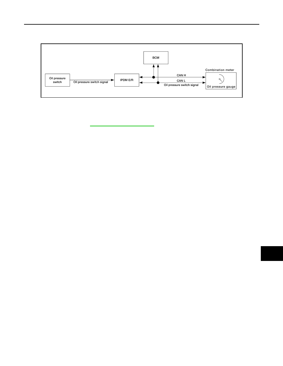
SIGNAL BUFFER SYSTEM
System Diagram
INFOID:0000000001697584
System Description
INFOID:0000000001697585
IPDM E/R reads the status of the oil pressure switch and transmits the oil pressure switch signal to BCM via
CAN communication. Refer to
.
AWNIA0174GB