содержание .. 43 44 45 46 ..
Nissan Tiida C11. Manual - part 45
BCS-44
< ECU DIAGNOSIS >
BCM (BODY CONTROL MODULE)
24
(O)
Ground
Ignition power sup-
ply
Input
Ignition switch OFF or ACC
0V
Ignition switch ON or START
Battery voltage
25
(L)
Ground
Door lock/unlock
switch (Unlock)
Output
Door lock/un-
lock switch
Not pressed
5V
Pressed to the unlock side
0V
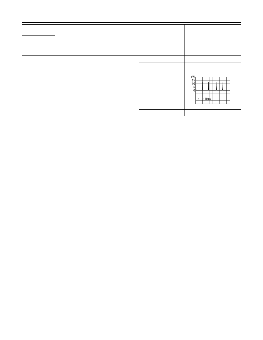
26
(L)
Ground
Hazard switch
Output
Hazard switch
Not pressed
Pressed
0V
Terminal No.
(Wire color)
Description
Condition
Reference Value
(Approx.)
Signal name
Input/
Output
+
−
SKIA2239J