Nissan Tiida C11. Manual - part 23


  Главная      Nissan     Nissan Tiida C11 - Service Manual


поиск по сайту            


содержание   ..  21  22  23  24   ..


Nissan Tiida C11. Manual - part 23


AV-86

< COMPONENT DIAGNOSIS >

[AUDIO WITH NAVIGATION]

RGB AREA (YS) SIGNAL CIRCUIT

RGB AREA (YS) SIGNAL CIRCUIT

Description

INFOID:0000000001728735

Transmits the display area of RGB image displayed by NAVI control unit with RGB area (YS) signal to display
unit.

Diagnosis Procedure

INFOID:0000000001728736

1.

CHECK CONTINUITY RGB AREA (YS) SIGNAL CIRCUIT

1.

Turn ignition switch OFF.

2.

Disconnect display unit connector and NAVI control unit connector.

3.

Check continuity between display unit harness connector terminal 2 and NAVI control unit harness con-
nector terminal 50.

4.

Check continuity between display unit harness connector terminal 2 and ground.

Is inspection result OK?

YES

>> GO TO 2.

NO

>> Repair harness or connector.

2.

CHECK RGB SYNCHRONIZING SIGNAL

1.

Connect display unit connector and NAVI control unit connector.

2.

Turn ignition switch ON.

3.

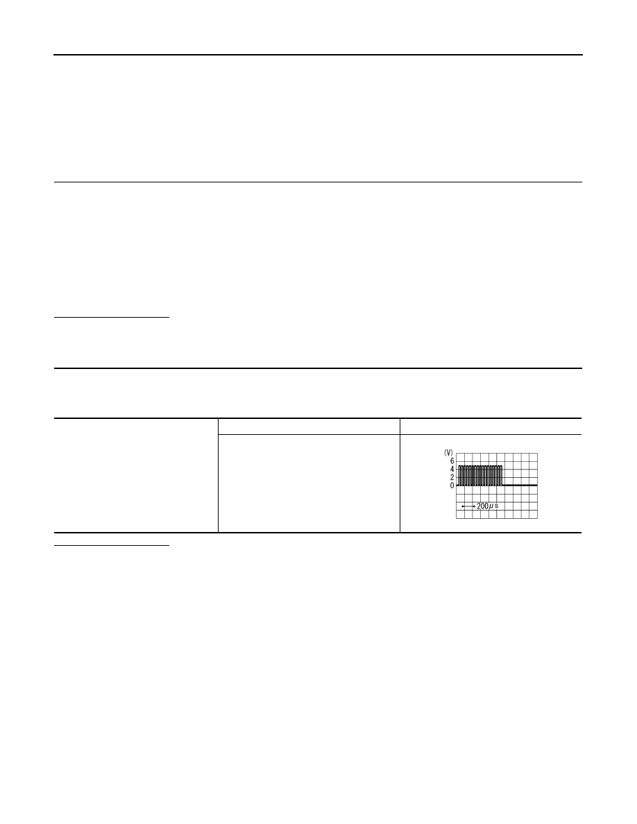
Check signal between display unit harness connector terminal 2 and ground.

Is inspection result OK?

YES

>> Replace display unit.

NO

>> Replace NAVI control unit.

2 - 50

: Continuity should exist.

2 - Ground

: Continuity should not exist.

2 - Ground

At RGB image displayed

: Approx. 5 V

At rear view camera image displayed

PKIB4948J

AV

HORIZONTAL SYNCHRONIZING (HP) SIGNAL CIRCUIT

AV-87

< COMPONENT DIAGNOSIS >

[AUDIO WITH NAVIGATION]

C

D

E

F

G

H

I

J

K

L

M

B

A

O

P

HORIZONTAL SYNCHRONIZING (HP) SIGNAL CIRCUIT

Description

INFOID:0000000001728737

In composite image (camera image), it transmits the vertical synchronizing (VP) signal and horizontal synchro-
nizing (HP) signal from display unit to NAVI control unit so as to synchronize the RGB images displayed with
NAVI control unit such as the image quality adjusting menu, etc.

Diagnosis Procedure

INFOID:0000000001728738

1.

CHECK CONTINUITY HORIZONTAL SYNCHRONIZING (HP) SIGNAL CIRCUIT

1.

Turn ignition switch OFF.

2.

Disconnect display unit connector and NAVI control unit connector.

3.

Check continuity between display unit harness connector terminal 4 and NAVI control unit harness con-
nector terminal 51.

4.

Check continuity between display unit harness connector terminal 4 and ground.

Is inspection result OK?

YES

>> GO TO 2.

NO

>> Repair harness or connector.

2.

CHECK HORIZONTAL SYNCHRONIZING (HP) SIGNAL

1.

Connect display unit connector and NAVI control unit connector.

2.

Turn ignition switch ON.

3.

Check signal between display unit harness connector terminal 4 and ground.

Is inspection result OK?

YES

>> Replace NAVI control unit.

NO

>> Replace display unit.

4 - 51

: Continuity should exist.

4 - Ground

: Continuity should not exist.

4 - Ground

SKIB0825E

AV-88

< COMPONENT DIAGNOSIS >

[AUDIO WITH NAVIGATION]

VERTICAL SYNCHRONIZING (VP) SIGNAL CIRCUIT

VERTICAL SYNCHRONIZING (VP) SIGNAL CIRCUIT

Description

INFOID:0000000001728739

In composite image (camera image), it is transmits the vertical synchronizing (VP) signal and horizontal syn-
chronizing (HP) signal from display unit to NAVI control unit so as to synchronize the RGB images displayed
with NAVI control unit such as the image quality adjusting menu, etc.

Diagnosis Procedure

INFOID:0000000001728740

1.

CHECK CONTINUITY VERTICAL SYNCHRONIZING (VP) SIGNAL CIRCUIT

1.

Turn ignition switch OFF.

2.

Disconnect display unit connector and NAVI control unit connector.

3.

Check continuity between display unit harness connector terminal 6 and NAVI control unit harness con-
nector terminal 52.

4.

Check continuity between display unit harness connector terminal 6 and ground.

Is inspection result OK?

YES

>> GO TO 2.

NO

>> Repair harness or connector.

2.

CHECK VERTICAL SYNCHRONIZING (VP) SIGNAL

1.

Connect display unit connector and NAVI control unit connector.

2.

Turn ignition switch ON.

3.

Check signal between display unit harness connector terminal 6 and ground.

Is inspection result OK?

YES

>> Replace NAVI control unit.

NO

>> Replace display unit.

6 - 52

: Continuity should exist.

6 - Ground

: Continuity should not exist.

6 - Ground

SKIB0823E

AV

STEERING SWITCH

AV-89

< COMPONENT DIAGNOSIS >

[AUDIO WITH NAVIGATION]

C

D

E

F

G

H

I

J

K

L

M

B

A

O

P

STEERING SWITCH

Description

INFOID:0000000001728775

When one of the steering wheel AV control switches is pushed, the resistance in the steering wheel AV control
switch circuit changes depending on which button is pushed.

Diagnosis Procedure

INFOID:0000000001728776

1.

CHECK STEERING WHEEL AUDIO CONTROL SWITCH RESISTANCE

1.

Disconnect steering wheel audio control switch connector M102.

2.

Check resistance between steering switch connector terminals.

Do the steering wheel audio control switches check OK?

YES

>> GO TO 2

NO

>> Replace steering wheel audio control switch. Refer to 

XX-XX, "*****"

.

2.

CHECK HARNESS

1.

Turn ignition switch OFF.

2.

Disconnect AV control unit connector M42 and spiral cable con-
nector M30.

3.

Check continuity between AV control unit harness connector
M42 (A) and spiral cable harness connector M30 (B).

4.

Check continuity between AV control unit connector M42 (A) and ground.

Are the continuity results as specified?

YES

>> GO TO 3

NO

>> Repair harness.

3.

SPIRAL CABLE CHECK

Terminal

Signal name

Condition

Resistance 

(

)

(Approx.)

16

17

Seek (down)

Depress  

switch.

165

Volume (down)

Depress VOL down switch.

487

Power

Depress PWR switch.

0

20

17

Seek (up)

Depress  

switch.

165

Volume (up)

Depress VOL up switch.

487

Mode

Depress MODE switch.

0

WKIA4457E

A

Continuity

Connector

Terminal

Connector

Terminal

M42

6

M30

24

Yes

15

31

16

32

A

Continuity

Connector

Terminal

M42

6

Ground

No

15

16

ALNIA0332GB


содержание   ..  21  22  23  24   ..