Nissan Tiida C11. Manual - part 12


  Главная      Nissan     Nissan Tiida C11 - Service Manual


поиск по сайту            


содержание   ..  10  11  12  13   ..


Nissan Tiida C11. Manual - part 12


AV-42

< FUNCTION DIAGNOSIS >

[AUDIO WITH NAVIGATION]

DIAGNOSIS SYSTEM (NAVI CONTROL UNIT)

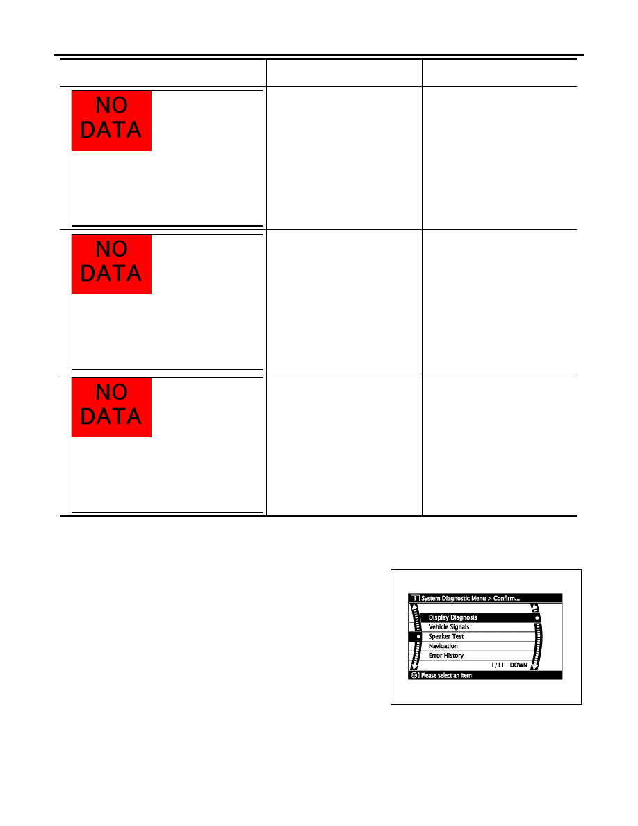
COMFIRMATON/ADJUSTMENT MODE

1.

Start the diagnosis function and select “Confirmation / Adjustment”. The confirmation/adjustment mode
indicates where each item can be checked or adjusted.

2.

Select each switch on the “Confirmation / Adjustment Mode”
screen to display the relevant trouble diagnosis screen. Press
the “BACK” switch to return to the initial “Confirmation / Adjust-
ment Mode” screen.

Malfunction is detected on communi-
cation signal between NAVI control 
unit and audio unit.

• NAVI  control  unit
• Audio unit

GPS antenna connection malfunction 
is detected.

• GPS antenna
• GPS antenna feeder

Malfunction is detected on communi-
cation signal between NAVI control 
unit and display unit.

• NAVI  control  unit
• Display unit

Area with yellow connection lines

Description

Possible malfunction location / Action 

to take

ALNIA0887GB

ALNIA0888GB

ALNIA0889GB

SKIB4658E

AV

DIAGNOSIS SYSTEM (NAVI CONTROL UNIT)

AV-43

< FUNCTION DIAGNOSIS >

[AUDIO WITH NAVIGATION]

C

D

E

F

G

H

I

J

K

L

M

B

A

O

P

Display Diagnosis

The tint of the color bar indication is as per the following list if RGB signal error is detected.

Vehicle Signals

A comparison check can be made of each actual vehicle signal and
the signals recognized by the system.

Speaker Test

JPNIA0169GB

R (red) signal error

: Light blue (Cyan) tint

G (green) signal error

: Purple (Magenta) tint

B (blue) signal error

: Yellow tint

SKIB3663E

Diagnosis item

Display

Vehicle status

Remarks

Vehicle speed

ON

Vehicle speed > 0 km/h (0 MPH)

Changes in indication may be delayed by approximate-
ly 1.5 seconds. This is normal.

OFF

Vehicle speed = 0 km/h (0 MPH)

Ignition switch ACC

Parking brake

ON

Parking brake is applied.

OFF

Parking brake is released.

Lights

ON

Light switch ON

OFF

Light switch OFF

Ignition

ON

Ignition switch ON

OFF

Ignition switch in ACC position

Reverse

ON

Selector lever in R position

Changes in indication may be delayed by approximate-
ly 1.5 seconds. This is normal.

OFF

Selector lever in any position other 
than R

Ignition switch ACC

AV-44

< FUNCTION DIAGNOSIS >

[AUDIO WITH NAVIGATION]

DIAGNOSIS SYSTEM (NAVI CONTROL UNIT)

Select “SPEAKER TEST” to display the Speaker Diagnosis screen.
Press “START and NEXT” to generate a test tone in a speaker.
Press “Start” to generate a test tone in the next speaker. Press
“Stop” to stop the test tones.
NOTE:
The frequency of test tone emitted from each speaker is as follows.

Navigation

STEERING ANGLE ADJUSTMENT
The steering angle output value detected with the gyroscope is
adjusted.

SPEED CALIBRATION
During normal driving, distance error caused by tire wear and tire
pressure change is automatically adjusted for by the automatic dis-
tance correction function. This function, on the other hand, is for
immediate adjustment, in cases such as driving with tire chain fitted
on tires.

ERROR HISTORY

The diagnostic results of “Self-diagnosis” determine if any malfunction occurred between selecting “Self-diag-
nosis” and displaying “Self-diagnostic Results”.
The trouble diagnosis result will be judged normal if an error occurred before the ignition switch was turned
ON and does not occur again until “Self-diagnosis” is completed. Therefore, errors in the past which cannot be
found by “Self-diagnosis”, must be found by checking the “Error record”.
The error history shows the error occurrence frequency in past. The frequency of occurrence is displayed by 2
types: the count down type and the count up type. Select either type according to the error item.
In “Error History” of models with NAVI, time and place that the selected error last occurred are displayed. Be
careful about the following.
• The correct date of occurrence may not be able to be displayed if there is a malfunction with the GPS

antenna circuit board in the NAVI control unit.

• Place of the error occurrence is represented by the position of the current location mark at the time an error

occurred. If current location mark has deviated from the correct position, then the place of the error occur-
rence cannot be located correctly.

Tweeter

: 3 kHz

Front door speaker

: 300 Hz

Rear door speaker

: 1 kHz

SKIB4686E

SKIB3684E

SKIB3685E

AV

DIAGNOSIS SYSTEM (NAVI CONTROL UNIT)

AV-45

< FUNCTION DIAGNOSIS >

[AUDIO WITH NAVIGATION]

C

D

E

F

G

H

I

J

K

L

M

B

A

O

P

Transition Screen

Count Down Type

• Set the counter to 40 when the error is detected. The counter decreases by 1 if the system is normal when

turning the ignition switch ON.

• The lower limit of the counter is 1. It can be reset to 0 by “Delete log” switch or CONSULT-III.

Count Up Type

• The counter increases 1 when the ignition switch is turned ON and the error is detected. The counter does

not decrease even if it is normal when the ignition switch is turned ON the next time.

• The upper limit of the counter is 50. 51 or more is displayed as 50. It can be reset to 0 by “Delete log” switch

or CONSULT-III.

Error Item

• Some error items may be displayed simultaneously according to the cause. The detection of the cause can

be performed by the combination of display items if some error items are displayed simultaneously.

SKIB3687E

Display type of occur-

rence frequency

Error history display item

Count down type

CAN_COMM_CIRCUIT, CONTROL UNIT (CAN), AV COMM CIRCUIT, CONTROL UNIT (AV)

Count up type

Other than the above

Error item

Description

Possible cause/Action to take

CAN_COMM_CIRCUIT

CAN communication malfunction is de-
tected.

Perform the diagnosis using CONSULT-III, 
and then repair the malfunctioning parts 
based on diagnostic results.
Refer to 

AV-48, "CONSULT - III Function 

(MULTI AV)"

.

CONTROL UNIT (CAN) 

CAN initial diagnosis malfunction is de-
tected.

NAVI control unit

CONTROL UNIT (AV) 

AV communication circuit initial diagno-
sis malfunction is detected. 

NAVI control unit

• AV COMM CIRCUIT
• Switches Connection Error
• Audio Unit Connection Error
• Amplifier Connection Error
• RDS-TMC Error

• Audio unit power supply and ground 

circuit malfunction is detected.

• Malfunction is detected on communi-

cation circuit between Audio unit and 
NAVI control unit.

• Malfunction is detected on communi-

cation signal between audio unit and 
NAVI control unit.

• Audio unit power supply and ground cir-

cuit

• Communication circuit between audio 

unit and NAVI control unit


содержание   ..  10  11  12  13   ..