Mitsubishi Outlander XL. Manual - part 697
ASC OFF SWITCH
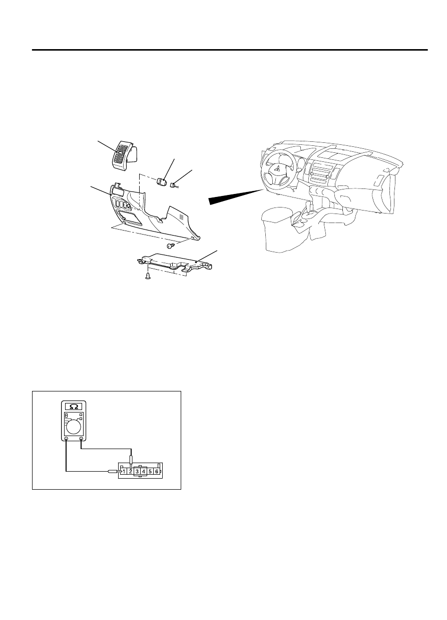
REMOVAL AND INSTALLATION
M13506100107USA0000010000
NOTE:
Refer to GROUP 52A - Instrument Panel
Assembly for the clip location P.52A-7.
ZC6009980000
1
2
3
5
4
Removal steps
1.
Bottom cover assembly (driver side)
2.
Side air outlet
3.
Lower panel assembly
Removal steps
4.
ASC OFF switch connector
5.
ASC OFF switch
INSPECTION
M13506100108USA0000010000
ASC OFF SWITCH CONTINUITY CHECK
ZC6009990000
1.
As shown in the figure, connect the circuit tester to the ASC
OFF switch terminals No. 1 and No. 2 as a single unit.
2.
If continuity is detected when the ASC OFF switch is pressed
and if not detected when the switch is released, the ASC OFF
switch is in good condition.
ACTIVE SKID CONTROL SYSTEM (ASC)
35C-195
ASC OFF SWITCH