Mitsubishi Outlander XL. Manual - part 542


  Index      Mitsubishi     Mitsubishi Outlander XL - service repair manual 2007 year


Search            


Content   ..  540  541  542  543   ..


Mitsubishi Outlander XL. Manual - part 542


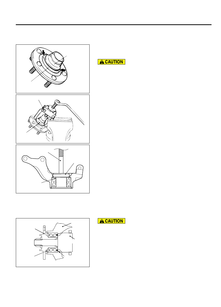
<<B>> WHEEL BEARING REMOVAL

ZC5018800000

Inner race 
(outside)

Outer
oil seal

1.

Deform the outer oil seal in the area shown in the figure with
a screwdriver to engage the special tool tab with the wheel
bearing inner race (outside).

When  the  inner  race  (outside)  has  been  pulled  out,  be
careful not to drop the hub.

ZC5018810000

MB990810

Inner race
(outside)

2.

Use special tool MB990810 to remove the wheel bearing inner
race (outside) from the hub.

ZC5018820000

MB990938

MB990935

Inner race
(outside)

3.

Assemble the inner race (outside) removed from the hub to
the  wheel  bearing,  and  use  the  following  special  tools
MB990935 and MB990938 to remove the wheel bearing.

ASSEMBLY SERVICE POINT

>>A<< WHEEL BEARING INSTALLATION

ZC5000820000

Knuckle

Hub

Oil seal
(light gold)

Encoder
(Dark brown)

Driveshaft

The magnetic encoder for wheel speed sensor is installed
in the wheel bearing. Install the wheel bearing so that the
encoder is positioned in the direction shown in the figure.

When press-fit the wheel bearing, push the outer race.

FRONT AXLE

26-15

FRONT AXLE HUB ASSEMBLY

ZC5018830000

MB990890

MB990883

Use  special  tools  MB990883  and  MB  990890  to  press-fit  the
wheel bearing.


>>B<< DUST COVER INSTALLATION

ZC6013110000

MB991576

MB991388

Bolt

Dust cover

Use  special  tools  MB991388  and  MB991576  to  press-fit  the
knuckle into the dust cover.

NOTE: 

Use the bolts (M12) to align the caliper mounting

holes.


>>C<< HUB ROTATION STARTING TORQUE CHECK

AC210315

ZC5018840000

MB991000

MB991017

Tighten the nut with 
the bolt secured

1.

Set special tools MB991000 and MB991017 as shown in the
figure, tighten the nut to the specified torque, and press-fit the
hub into the knuckle.

Tightening torque: 160 ± 16 N·m (118 ± 11 in-lb)

2.

Rotate the hub to make the bearing well-greased.

26-16

FRONT AXLE

FRONT AXLE HUB ASSEMBLY

ZC5018850000

MB990326

3.

Use  Special  tool  MB990326  to  measure  the  hub  rotation
starting torque.

Limit: 1.8 N·m (16 in-lb)

4.

Hub rotation starting torque should be within the limit value,
and there should be no roughness and gritty feeling in rotation.


>>D<< WHEEL BEARING END PLAY CHECK

ZC5018860000

MB991017

MB991000

Tighten the nut 
with the bolt 
secured

1.

Use special tools MB991000 and MB991017 to measure to
determine whether the wheel bearing end play is within the
specified limit or not.

Limit: 0.05 mm(0.002 inch)

2.

If  the  end  play  is  not  within  the  limit  range  while  the  nut  is
tightened to specified torque, the bearing, hub and/or knuckle
have  probably  not  been  installed  correctly.  Replace  the
bearing and re-install.

Tightening torque: 160 ± 16 N·m (118 ± 11 in-lb)

INSPECTION

M12601000020USA0000010000

Check  the  front  hub  and  brake  disc  mounting  surfaces  for
galling and contamination.

Check the knuckle inner surface for galling and cracks.

DRIVESHAFT ASSEMBLY

REMOVAL AND INSTALLATION

M12601000035USA0000010000

The  magnetic  encoder  collects  metallic
particles easily, because it is magnetized. Make
sure  that  the  magnetic  encoder  should  not
collect metallic particles. Check that there is not
any trouble prior to reassembling it.

When  removing  and  installing  the  driveshaft
assembly,  make  sure  that  the  wheel  speed
detection magnetic encoder (integrated with the
inner  oil  seal)  does  not  contact  with
surrounding parts to avoid damage.

When  removing  and  installing  the  front  wheel
speed sensor, make sure that the pole piece at
the end does not contact with surrounding parts
to avoid damage.

The parts indicated by * are the nuts with friction
coefficient stabilizer. In removal, ensure there is
no  damage,  clean  dust  and  soiling  from  the
bearing and thread surfaces, and tighten them
to the specified torque.

Pre-removal operation

Transmission  Fluid  Draining  (Refer  to  GROUP  23A,  On-

vehicle Service, Transmission Fluid Change P.23A-153.)

Post-installation operation

Using your fingers, press the Ball Joint Dust Cover to check

for a crack or damage.

FRONT AXLE

26-17

FRONT AXLE HUB ASSEMBLY

Transmission Fluid Filling (Refer to GROUP 23A, On-vehicle

Service, Transmission Fluid Change P.23A-153.)

ZC5018870000

N

3

1

4

13 ± 2 N·m
111 ± 22 in-lb

71 ± 10 N·m
52 ± 7 ft-lb

144 - 176 N·m
107 - 129 ft-lb

N

2

<LH>

<FWD-RH>

N

N

8.5 ± 1.5 N·m
76 ± 13 in-lb

10

5

6

9

11

12

39 ± 6 N·m
29 ± 4 ft-lb

25 ± 5 N·m
19 ± 3 ft-lb

11

N

12

*

<AWD-RH>

40 ± 4 N·m
30 ± 3 ft-lb

11

8

7

9.5 ± 2.5 N·m
84 ± 22 in-lb

Removal steps

1.

Cotter pin

<<A>>

>>B<<

2.

Driveshaft nut

>>B<<

3.

Washer

4.

Front wheel speed sensor

5.

Front  wheel  speed  sensor  harness
bracket

6.

Brake hose bracket

7.

Front  height  sensor  to  lower  arm
connection

Removal steps

8.

Stabilizer link connection

9.

Self-locking nut (lower arm ball joint
connection)

<<B>>

10. Self-locking

 nut

 (tie-rod

 end

connection)

<<C>>

>>A<<

11. Driveshaft assembly
12. Circlip

Required Special Tools:

MB990242: Puller Shaft

MB990244: Puller Bar

MB990767: Front Hub and Flange Yoke Holder

MB991000: Spacer

MB991017: Front Hub Remover and Installer

MB991354: Puller Body

MB991897 or MB992011: Ball Joint Remover

26-18

FRONT AXLE

DRIVESHAFT ASSEMBLY


Content   ..  540  541  542  543   ..