Mitsubishi Outlander XL. Manual - part 293
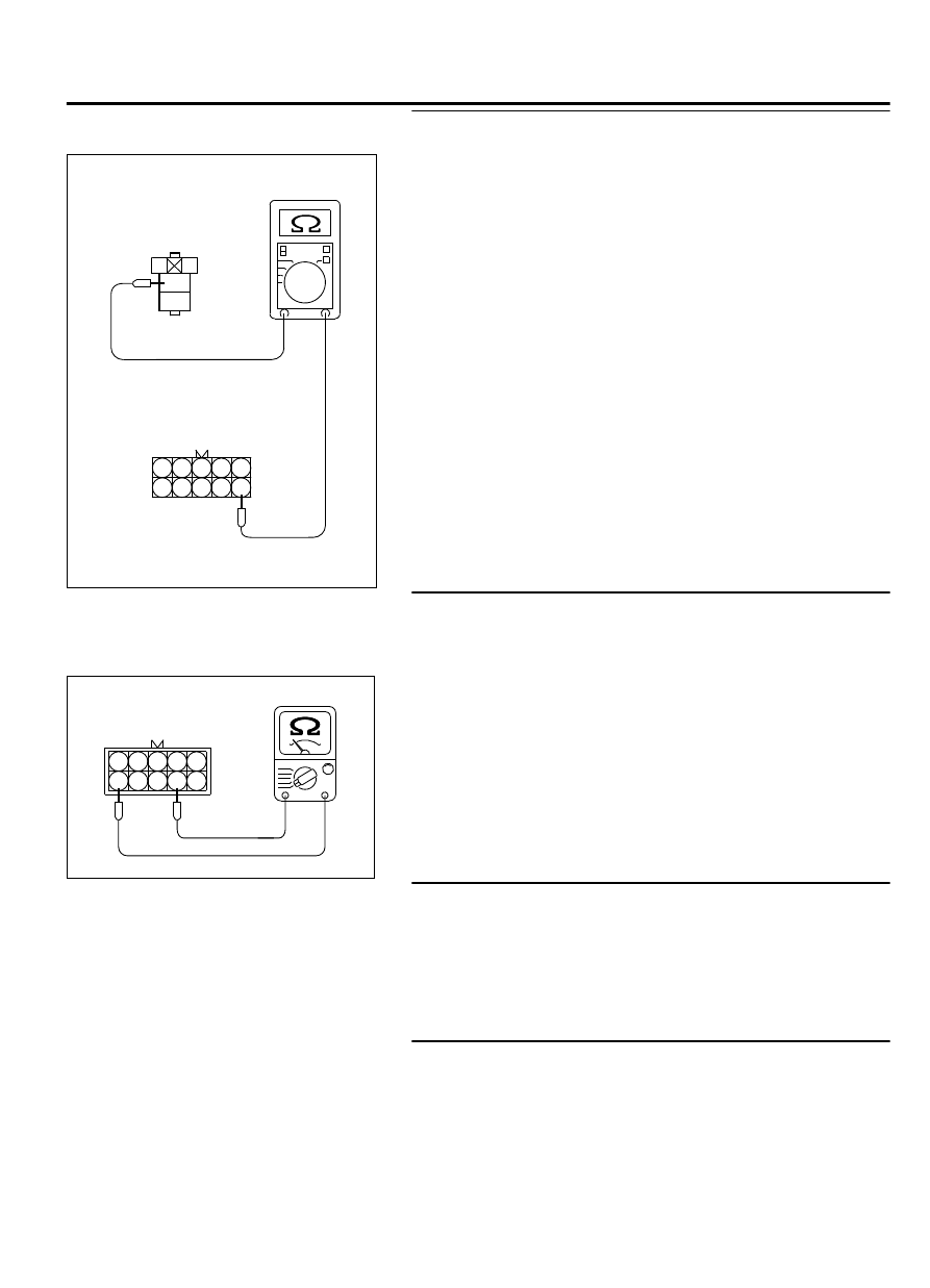
STEP 4. Check for harness between the injector relay
connector A-24X and the intermediate connector B-21.
2
1
3
4
1
2
3
4
5
6
7
8
9
10
ZK603327
A-24X Harness
connector:
component side
B-21 Harness
connector:
component side
AA00
(1)
Disconnect the injector relay connector A-24X and the
intermediate connector B-21.
(2)
Measure the resistance injector relay connector A-24X
(terminal No. 3) and the intermediate connector B-21
(terminal No. 6).
⦆
Should be less than 2 ohms.
Q:Is the harness wire in good condition?
YES:
Go to Step 9.
NO:
Repair it. Then go to Step 10.
STEP 5. Check the No. 5 cylinder injector resistance at
intermediate connector B-21.
(1)
Disconnect the intermediate connector B-21 and measure at
male connector side.
5
4
3
2
1
10
9
8
7
6
ZK603353
B-21
Intermediate
connector
AA00
(2)
Measure the resistance between terminal No. 6 and No. 9.
⦆
Resistance should be between 10.5 and 13.5 ohms.
Q:Is the measured resistance between 10.5 and 13.5 ohms?
YES:
Go to Step 8.
NO:
Go to Step 6.
STEP 6. Check the harness connector B-104 at No. 5
cylinder injector for damage.
Remove the intake manifold.
Q:Is the harness connector in good condition?
YES:
Go to Step 7.
NO:
Repair it. Refer to GROUP 00E, Harness Connector
Inspection P.00E-2. Then go to Step 10.
STEP 7. Check the No. 5 cylinder injector B-104.
(1)
Disconnect the No. 5 cylinder injector connector B-104.
MULTIPORT INJECTION SYSTEM (MFI) <DIAGNOSIS>
13Ab-367
DIAGNOSTIC TROUBLE CODE PROCEDURES