Mitsubishi Outlander XL. Manual - part 251
TROUBLESHOOTING HINTS (The most likely
causes for this code to be set are: )
⦆
Right bank heated oxygen sensor (front) failed.
⦆
Harness damage
⦆
Connector damage.
⦆
ECM failed.
DIAGNOSIS
Required Special Tools:
⦆
MB991958: Scan tool (M.U.T.-III Sub Assembly)
⦆
MB991824: V.C.I.
⦆
MB991827: USB Cable
⦆
MB991910: Main Harness A
⦆
MB991316: Test Harness
STEP 1. Check harness connector B-03 at the right bank
heated oxygen sensor (front) harness connector B-10 at the
ECM for damage.
Q:Is the harness connector in good condition?
YES:
Go to Step 2.
NO:
Repair or replace it. Refer to GROUP 00E, Harness
Connector Inspection P.00E-2. Then go to Step 5.
STEP 2. Check the right bank heated oxygen sensor (front).
(1)
Disconnect the right bank heated oxygen sensor (front)
connector B-03 and connect test harness special tool,
MB991316, to the connector on the right bank heated oxygen
sensor (front) side.
(2)
Warm up the engine until engine coolant temperature
reaches 80°C (176°F) or higher.
(3)
Rev the engine for 5 minutes or more with the engine speed
of 2,500 r/min.
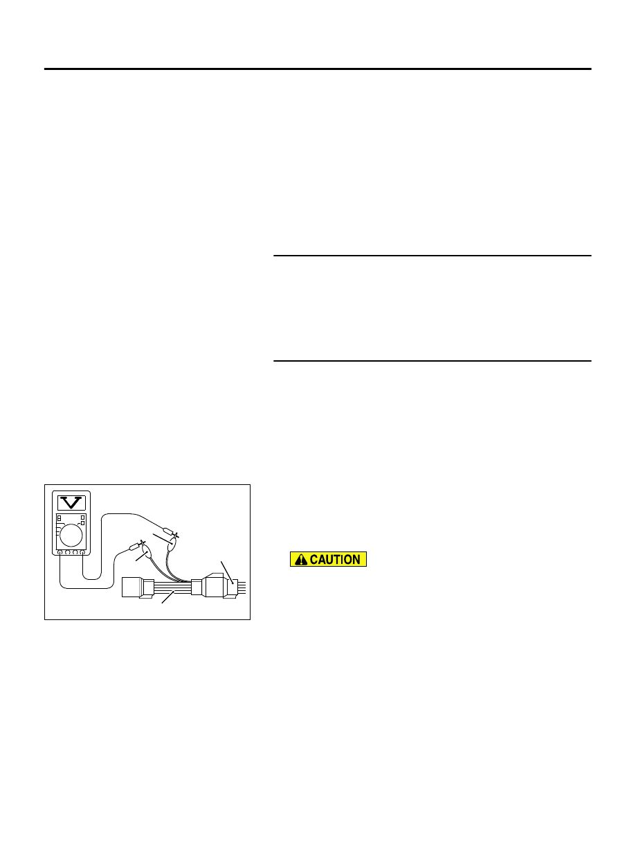
ZK604077
Heated
oxygen
sensor
component
side
connector
MB991316
Black
White
AA00
(4)
Connect a digital voltage meter between terminal No. 2 (black
clip) and terminal No. 4 (white clip).
(5)
While repeatedly revving the engine, measure the right bank
heated oxygen sensor (front) output voltage.
Standard value: 0.6 - 1.0 volts
⦆
Be very careful when connecting the jumper wires;
incorrect connection can damage the heated oxygen
sensor.
⦆
Be careful the heater can be damaged if a voltage
beyond 8 volts is applied to the heated oxygen sensor
heater.
NOTE:
If the sufficiently high temperature [of
approximate 400°C (752°F) or more] is not reached
although the heated oxygen sensor is normal, the output
voltage would be possibly low although the rich air/fuel
ratio. Therefore, if the output voltage is low, use a
jumper wire to connect the terminal No.1 (red clip) and
the terminal No. 3 (blue clip) of the heated oxygen
sensor with the positive terminal and the negative
MULTIPORT INJECTION SYSTEM (MFI) <DIAGNOSIS>
13Ab-199
DIAGNOSTIC TROUBLE CODE PROCEDURES