Mitsubishi Outlander XL. Manual - part 235
DIAGNOSIS
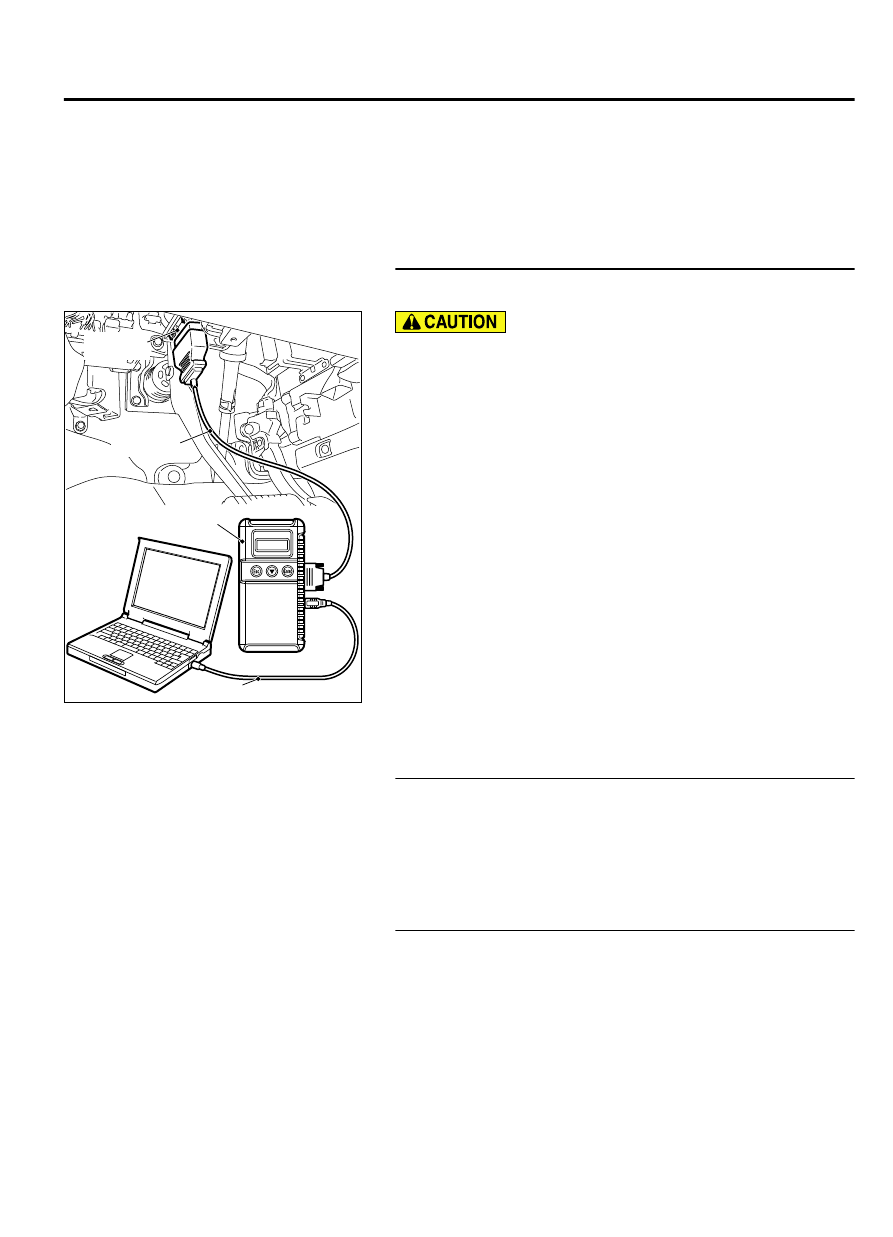
Required Special Tools:
⦆
MB991958: Scan Tool (M.U.T.-III Sub Assembly)
⦆
MB991824: V.C.I.
⦆
MB991827: USB Cable
⦆
MB991910: Main Harness A
STEP 1. Using scan tool MB991958, check data list item 8:
Manifold Absolute Pressure Sensor.
ZC501967
AC404789
ZC5019680000
MB991824
MB991827
MB991910
Data link
connector
To prevent damage to scan tool MB991958, always turn the
ignition switch to the "LOCK" (OFF) position before
connecting or disconnecting scan tool MB991958.
(1)
Connect scan tool MB991958 to the data link connector.
(2)
Turn the ignition switch to the "ON" position.
(3)
Set scan tool MB991958 to the data reading mode for item
8, Manifold Absolute Pressure Sensor.
⦆
When altitude is 0 m (0 foot), 101 kPa (29.8 in.Hg).
⦆
When altitude is 600 m (1,969 feet), 95 kPa (28.1 in.Hg).
⦆
When altitude is 1,200 m (3,937 feet), 88 kPa (26.0 in.Hg).
⦆
When altitude is 1,800 m (5,906 feet), 81 kPa (23.9 in.Hg).
(4)
Start the engine.
⦆
When the engine is idling, 16 - 36 kPa (4.7 - 10.6 in.Hg).
⦆
When the engine is suddenly revved, manifold absolute
pressure varies.
(5)
Turn the ignition switch to the "LOCK" (OFF) position.
Q:Is the sensor operating properly?
YES:
It can be assumed that this malfunction is
intermittent. Refer to GROUP 00, How to Use
Troubleshooting/Inspection Service Points - How to Cope
with Intermittent Malfunctions P.00-15.
NO:
Go to Step 2.
STEP 2. Check harness connector B-105 at the manifold
absolute pressure sensor and harness connector B-10 at
the ECM for damage.
Q:Is the harness connector in good condition?
YES:
Go to Step 3.
NO:
Repair it. Refer to GROUP 00E, Harness Connector
Inspection P.00E-2. Then go to Step 7.
STEP 3. Measure the sensor supply voltage at manifold
absolute pressure sensor connector B-105.
(1)
Disconnect the connector B-105.
(2)
Turn the ignition switch to the "ON" position.
MULTIPORT INJECTION SYSTEM (MFI) <DIAGNOSIS>
13Ab-135
DIAGNOSTIC TROUBLE CODE PROCEDURES