Content .. 1283 1284 1285 1286 ..
Mitsubishi Outlander XL. Manual - part 1285
CONSTRUCTION DESCRIPTION
SENSOR
M23501000010USA0000010000
WHEEL SPEED SENSOR
ZC6006670000
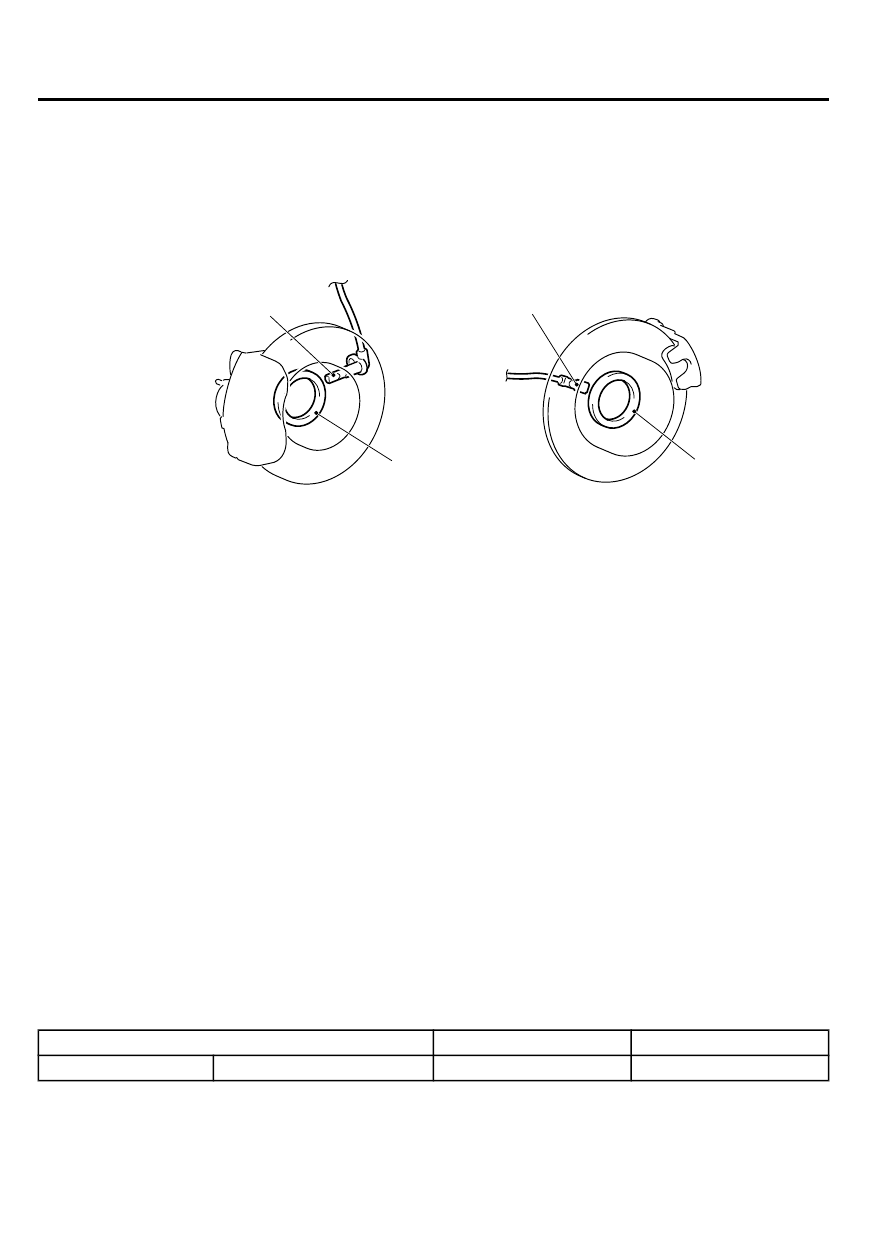
Front
Rear
Front wheel speed sensor
Rear wheel speed sensor
Encoder for
wheel speed detection
Encoder for
wheel speed detection
The wheel speed sensor is a kind of a pulse generator.
It consists of the magnetic encoder for wheel speed
detection (a plate on which north and south pole sides
of the magnets are arranged alternately) which rotates
at the same speed of the wheel and the wheel speed
sensor (semiconductor sensor). This sensor outputs
frequency pulse signals in proportion to the wheel
speed.
The front wheel speed sensor consists of the front
wheel speed sensor mounted on the knuckle and the
magnetic encoder for wheel speed detection which is
press-fitted together with the oil seal to the front wheel
bearing. The rear wheel speed sensor consists of the
rear wheel speed sensor mounted on the trailing arm
assembly and the magnetic encoder for wheel speed
detection, which is press-fitted together with the oil
seal to the rear wheel bearing.
G SENSOR <AWD>
The G-sensor is incorporated in ABS-ECU, and
detects longitudinal acceleration of a vehicle.
Actuator
M23501000020USA0000010000
ABS warning light, Brake warning light
The ABS system informs the driver to the ABS system
status by illuminating, extinguishing, or flashing the
ABS warning light and brake warning light as follows.
ABS warning light
⦆
Turns ON when the system malfunction occurs.
Brake warning light
⦆
Turns ON when the EBD system malfunction
occurs.
NOTE:
⦆
Turns ON when the brake fluid level in the
reservoir tank becomes the specified value or
lower than that.
⦆
Turns ON when the parking brake lever is pulled
and the brake is activated.
ABS warning light and brake warning light illumination or flashing pattern
State
ABS warning light
Brake warning light
Normal
Correct
-
-
35B-6
FOUR-WHEEL ANTI-LOCK BRAKE SYSTEM (4ABS)
CONSTRUCTION DESCRIPTION