Mitsubishi Outlander XL. Manual - part 1141


  Index      Mitsubishi     Mitsubishi Outlander XL - service repair manual 2007 year


Search            


Content   ..  1139  1140  1141  1142   ..


Mitsubishi Outlander XL. Manual - part 1141


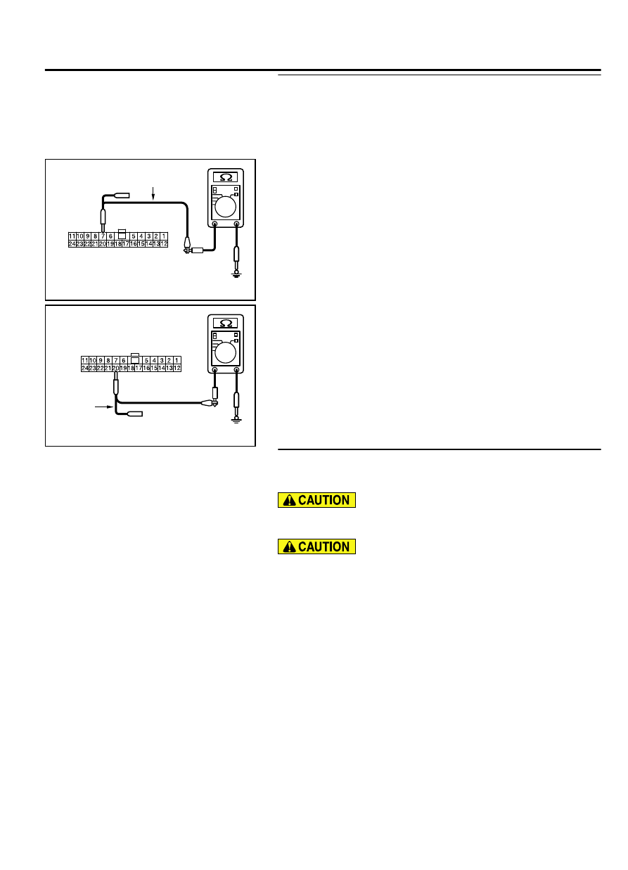
STEP 6. Check the wiring harness between joint connector
(CAN3) C-01 and TCM connector C-38 for a short to ground.
Measure the resistance at joint connector (CAN3) C-01.

(1)

Disconnect  joint  connector  (CAN3),  and  measure  the
resistance  at  the  wiring  harness  side  of  joint  connector
(CAN3).

ZC5010410012

Harness side: C-01

Test harness

(2)

Measure  the  resistance  between  joint  connector  (CAN3)
terminal 7 and body ground.

OK: 1 kiloohm or more

ZC5010410013

Harness side: C-01

Test 
harness

(3)

Measure  the  resistance  between  joint  connector  (CAN3)
terminal 20 and body ground.

OK: 1 kiloohm or more

Q:Do all the resistances measure 1 kiloohm or more?

YES:

 Check intermediate connector C-27, and repair if

necessary. If the intermediate connector is in good
condition, repair the wiring harness between joint
connector (CAN2) C-04 and joint connector (CAN3) C-01.

NO:

 Go to Step 12.

STEP 7. Using scan tool MB991958, diagnose the CAN bus
line. (checking the steering wheel sensor for internal short
to ground)

Strictly  observe  the  specified  wiring  harness  repair
procedure. For details refer to P.54D-8.

To prevent damage to scan tool MB991958, always turn the
ignition  switch  to  the  "LOCK"  (OFF)  position  before
connecting or disconnecting scan tool MB991958.

(1)

Disconnect steering wheel sensor connector C-209.

CONTROLLER AREA NETWORK (CAN)

54D-47

DIAGNOSIS

ZC501967

AC404789

ZC5019680000

MB991824

MB991827

MB991910

Data link

connector

(2)

Connect scan tool MB991958 to the data link connector.

(3)

Turn the ignition switch to the "ON" position.

ZC5018690001

: Red section on scree n

M. U . T .

J/C (3)

J/C (2)

SAS

4WD

K OS/WC

M

SRS

OCM

A/C

A UDI O

MMCS

Sat Radio

HFM

METER

ABS/ASC

A T

ENGINE

E T A C S

J/C (1)

(4)

Diagnose  CAN  bus  lines,  and  check  if  the  scan  tool
MB991958 screen is as shown in the figure.

OK:  The  display  of  the  scan  tool  MB991958  is  as
shown in the figure.

Q:Does  scan  tool  MB991958  screen  correspond  to  the

illustration?

YES:

 Repair the wiring harness between steering wheel

sensor connector C-209 and joint connector (CAN2) C-04.

NO:

 Check steering wheel sensor connector C-209, and

repair if necessary. If the steering wheel sensor
connector is in good condition, replace the steering
wheel sensor.

STEP 8. Using scan tool MB991958, diagnose the CAN bus
line. (checking the AWD-ECU for internal short to ground)

Strictly  observe  the  specified  wiring  harness  repair
procedure. For details refer to P.54D-8.

To prevent damage to scan tool MB991958, always turn the
ignition  switch  to  the  "LOCK"  (OFF)  position  before
connecting or disconnecting scan tool MB991958.

(1)

Disconnect AWD-ECU connector C-128.

54D-48

CONTROLLER AREA NETWORK (CAN)

DIAGNOSIS

ZC501967

AC404789

ZC5019680000

MB991824

MB991827

MB991910

Data link

connector

(2)

Connect scan tool MB991958 to the data link connector.

(3)

Turn the ignition switch to the "ON" position.

ZC5018690001

: Red section on scree n

M. U . T .

J/C (3)

J/C (2)

SAS

4WD

K OS/WC

M

SRS

OCM

A/C

A UDI O

MMCS

Sat Radio

HFM

METER

ABS/ASC

A T

ENGINE

E T A C S

J/C (1)

(4)

Diagnose  CAN  bus  lines,  and  check  if  the  scan  tool
MB991958 screen is as shown in the figure.

OK:  The  display  of  the  scan  tool  MB991958  is  as
shown in the figure.

Q:Does  scan  tool  MB991958  screen  correspond  to  the

illustration?

YES:

 Check intermediate connector C-31, and repair if

necessary. If the intermediate connector is in good
condition, repair the wiring harness between AWD-ECU
connector C-128 and joint connector (CAN2) C-04.

NO:

 Check AWD-ECU connector C-128, and repair if

necessary. If the AWD-ECU connector is in good condition,
replace the AWD-ECU.

STEP 9. Using scan tool MB991958, diagnose the CAN bus
line. (checking the ETACS-ECU for internal short to ground)

Strictly  observe  the  specified  wiring  harness  repair
procedure. For details refer to P.54D-8.

To prevent damage to scan tool MB991958, always turn the
ignition  switch  to  the  "LOCK"  (OFF)  position  before
connecting or disconnecting scan tool MB991958.

(1)

Disconnect ETACS-ECU connector C-301.

CONTROLLER AREA NETWORK (CAN)

54D-49

DIAGNOSIS

ZC501967

AC404789

ZC5019680000

MB991824

MB991827

MB991910

Data link

connector

(2)

Connect scan tool MB991958 to the data link connector.

(3)

Turn the ignition switch to the "ON" position.

ZC5018690001

: Red section on scree n

M. U . T .

J/C (3)

J/C (2)

SAS

4WD

K OS/WC

M

SRS

OCM

A/C

A UDI O

MMCS

Sat Radio

HFM

METER

ABS/ASC

A T

ENGINE

E T A C S

J/C (1)

(4)

Diagnose  CAN  bus  lines,  and  check  if  the  scan  tool
MB991958 screen is as shown in the figure.

OK:  The  display  of  the  scan  tool  MB991958  is  as
shown in the figure.

Q:Does  scan  tool  MB991958  screen  correspond  to  the

illustration?

YES:

 Repair the wiring harness between ETACS-ECU

connector C-301 and joint connector (CAN2) C-04.

NO:

 Check ETACS-ECU connector C-128, and repair if

necessary. If the ETACS-ECU connector is in good
condition, replace the ETACS-ECU.

STEP 10. Using scan tool MB991958, diagnose the CAN bus
line. (checking the ECM for internal short to ground)

Strictly  observe  the  specified  wiring  harness  repair
procedure. For details refer to P.54D-8.

To prevent damage to scan tool MB991958, always turn the
ignition  switch  to  the  "LOCK"  (OFF)  position  before
connecting or disconnecting scan tool MB991958.

(1)

Disconnect ECM connector B-11.

54D-50

CONTROLLER AREA NETWORK (CAN)

DIAGNOSIS


Content   ..  1139  1140  1141  1142   ..