Content .. 1101 1102 1103 1104 ..
Mitsubishi Outlander XL. Manual - part 1103
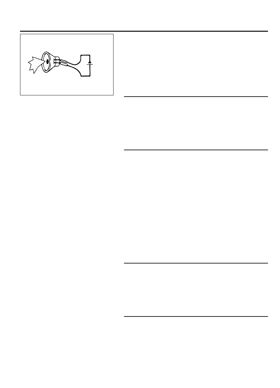
ZC3064660000
5 volts
(2)
Check that the rear door speaker (RH) outputs the noise
when the voltage of five volts is applied to the rear door
speaker (RH) connector terminal.
Q:Does the rear door speaker (RH) output the noise?
YES:
Go to Step 13.
NO:
Replace the rear door speaker (RH).
STEP 13. Check audio visual navigation unit connector C-10
for loose, corroded or damaged terminals, or terminals
pushed back in the connector.
Q:Is audio visual navigation unit connector C-10 in good
condition?
YES:
Go to Step 14.
NO:
Repair or replace the damaged component(s). Refer to
GROUP 00E, Harness Connector Inspection P.00E-2.
STEP 14. Check the wiring harness between audio visual
navigation unit connector C-10 (terminal 8, 16) and rear door
speaker (RH) connector E-24 (terminal 2, 1).
NOTE:
Also check intermediate connectors C-17, C-20 and
D-36 for loose, corroded, or damaged terminals, or
terminals pushed back in the connector. If intermediate
connector C-17, C-20 or D-36 is damaged, repair or replace
the connector as described in GROUP 00E, Harness Connector
Inspection P.00E-2.
⦆
Check the communication lines for open circuit.
Q:Is the wiring harness between audio visual navigation
unit connector C-10 (terminal 8, 16) and rear door speaker
(RH) connector E-24 (terminal 2, 1) in good condition?
YES:
Check the trouble symptom, and go to Step 27.
NO:
The wiring harness may be damaged or the connector
(s) may have loose, corroded or damaged terminals, or
terminals pushed back in the connector. Repair the wiring
harness as necessary.
STEP 15. Check rear door speaker (LH) connector E-10 for
loose, corroded or damaged terminals, or terminals pushed
back in the connector.
Q:Is rear door speaker (LH) connector E-10 in good
condition?
YES:
Go to Step 16.
NO:
Repair or replace the damaged component(s). Refer to
GROUP 00E, Harness Connector Inspection P.00E-2.
STEP 16. Check the rear door speaker (LH).
(1)
Remove the rear door speaker (LH). Refer to P.54B-170.
AUDIO AND NAVIGATION SYSTEM
54B-93
DIAGNOSIS