Mitsubishi Outlander GS45X. Manual - part 708
MULTIPORT FUEL INJECTION (MFI) DIAGNOSIS
TSB Revision
MULTIPORT FUEL INJECTION (MFI) <2.4L ENGINE>
13A-655
MONITOR EXECUTION CONDITIONS
(Other monitor and Sensor)
Other Monitor (There is no temporary DTC stored
in memory for the item monitored below)
• Not applicable
Sensor (The sensor below is determined to be
normal)
• Not applicable
.
DTC SET CONDITIONS <Range/Performance problem-relation between main and
sub>
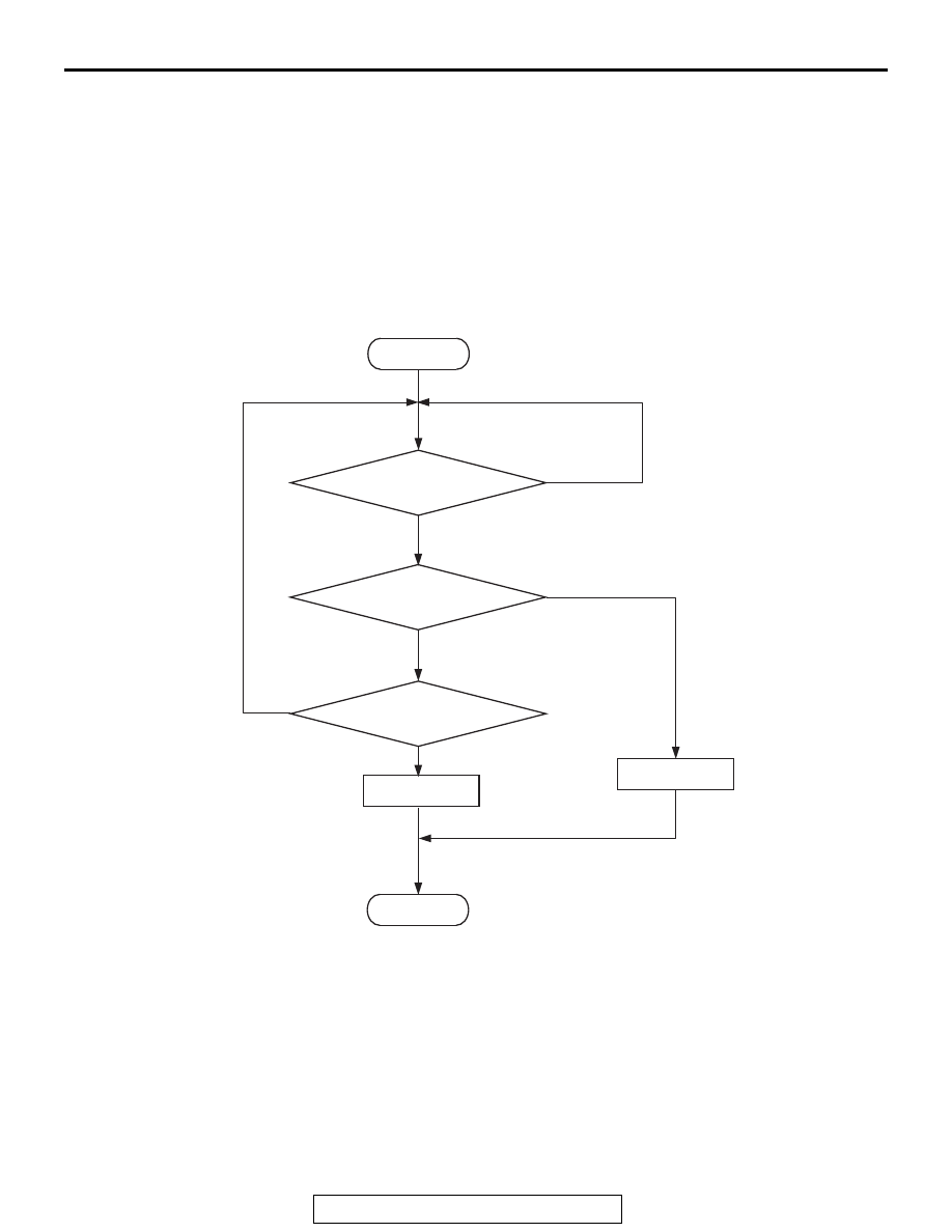
Logic Flow Chart
Check Conditions
• The target output voltage of the throttle position
sensor is 0.9 volt or less.
• Throttle position sensor (main) output voltage is
between 0.2 and 4.8 volts.
• Throttle position sensor (sub) output voltage is
between 0.2 and 4.8 volts.
• Battery positive voltage is higher than 8.3 volts.
Judgement Criterion
• Voltage obtained with the formula given below is
0.3 volt or higher for 0.3 second: [throttle position
sensor (main) voltage
− throttle position sensor
(sub) voltage]
NOTE: The throttle position sensor voltage used
for the judgement is converted into the throttle
position sensor voltage for the internal process-
ing by the ECM.
AK604361
Start
Yes
Yes
Yes
No
No
No
{TPS (main) - TPS (sub)}
>= 0.3V
Continuous
failure for 0.3sec
Malfunction
End
Good
Monitoring
conditions