Mitsubishi Outlander GS45X. Manual - part 627


  Index      Mitsubishi     Mitsubishi Outlander GS45X - service repair manual


Search            


Content   ..  625  626  627  628   ..


Mitsubishi Outlander GS45X. Manual - part 627


MULTIPORT FUEL INJECTION (MFI) DIAGNOSIS

TSB Revision

MULTIPORT FUEL INJECTION (MFI) <2.4L ENGINE>

13A-331

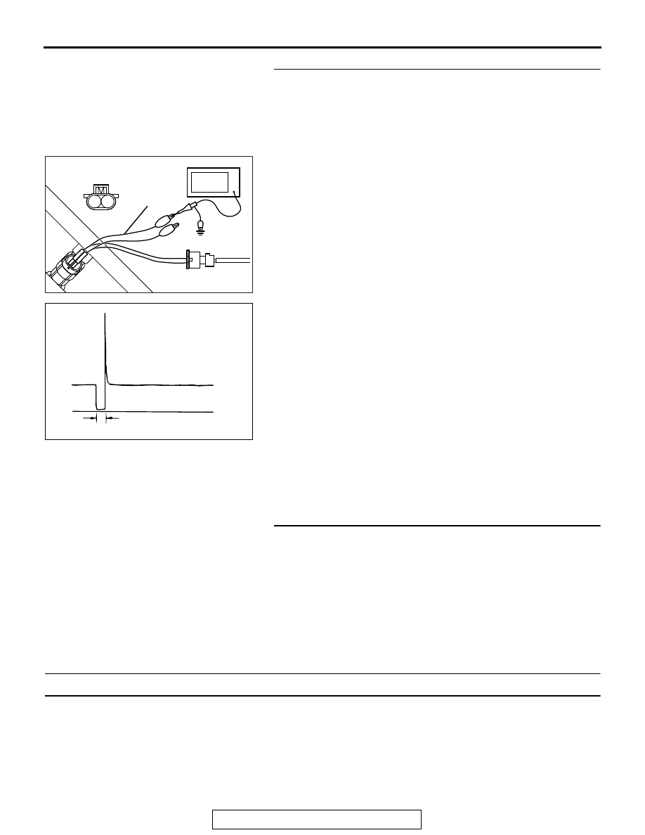
STEP 19. Using the oscilloscope, check the No. 4 cylinder 
injector.
(1) Disconnect the No. 4 cylinder injector connector B-116 and 

connect the test harness special tool MB991658 between 
the separated connectors. (All terminals should be 
connected.)

(2) Connect the oscilloscope probe to the injector side 

connector terminal No. 2.
NOTE: When measuring with the ECM side connector, dis-
connect all ECM connectors. Connect the check harness 
special tool (MB992110) between the separated connec-
tors. Then connect the oscilloscope probe to the check har-
ness connector terminal No. 19.

(3) Start the engine and run at idle.

(4) Measure the waveform.

• The waveform should show a normal pattern similar to 

the illustration.

(5) Turn the ignition switch to the "LOCK" (OFF) position.
Q: Is the waveform normal?

YES : It can be assumed that this malfunction is intermittent. 

Refer to GROUP 00, How to Use 
Troubleshooting/Inspection Service Points 

− How to 

Cope with Intermittent Malfunctions 

P.00-15

.

NO :  Replace the ECM. When the ECM is replaced, 

register the ID code. Refer to GROUP 42B, Diagnosis 
− ID Code Registration Judgment Table <Vehicles 

with KOS> 

P.42B-15

 or GROUP 42C, Diagnosis 

− ID 

Codes Registration Judgment Table <Vehicles with 
WCM> 

P.42C-10

. Then go to Step 20.

STEP 20. Test the OBD-II drive cycle.
(1) Carry out a test drive with the drive cycle pattern. Refer to 

Diagnostic Function 

− OBD-II Drive Cycle − Pattern 23 

P.13A-11

.

(2) Check the diagnostic trouble code (DTC). 
Q: Is DTC P0204 set?

YES : Retry the troubleshooting.
NO :  The inspection is complete.

DTC P0221: Throttle Position Sensor (Sub) Plausibility

.

TECHNICAL DESCRIPTION

Compare the actual measurement of volumetric effi-
ciency by a mass airflow sensor signal with volumet-
ric efficiency estimated from a throttle position 
sensor (sub) signal.

.

MONITOR EXECUTION

Continuous

.

AK604471

1 2

AB

Injector
connector

MB991658

Oscilloscope

AK604546 AB

A

Normal  waveform

A:Injector drivetime 

MULTIPORT FUEL INJECTION (MFI) DIAGNOSIS

TSB Revision

MULTIPORT FUEL INJECTION (MFI) <2.4L ENGINE>

13A-332

MONITOR EXECUTION CONDITIONS 
(Other monitor and Sensor)

Other Monitor (There is no temporary DTC stored 

in memory for the item monitored below)

• Not applicable

Sensor (The sensor below is determined to be 

normal)

• Not applicable

.

DTC SET CONDITIONS

Logic Flow Chart

Check Conditions

• The difference between the actual volumetric effi-

ciency and the volumetric efficiency estimated by 
the (sub) throttle position sensor is 0 percent or 
more. Or, the volumetric efficiency is 60 percent 
or less.

• The engine speed is between 750 and 3,000 

r/min. Or, the throttle position sensor (main) out-
put voltage is 3 volts or less.

AK604351

Start

Yes

Yes

Yes

No

No

No

Continuous failure

for specified time

Malfunction

End

Good

Monitoring
conditions

|Ec-calculated Ec| 
> specified value

Ec: load value

MULTIPORT FUEL INJECTION (MFI) DIAGNOSIS

TSB Revision

MULTIPORT FUEL INJECTION (MFI) <2.4L ENGINE>

13A-333

Judgment Criterion

• For 0.4 second, the difference between the actual 

volumetric efficiency and the volumetric efficiency 
estimated by the throttle position sensor (sub) is 
33 percent or more. 

.

OBD-II DRIVE CYCLE PATTERN

Refer to Diagnostic Function 

− OBD-II Drive Cycle 

Pattern 17 

P.13A-11

.

.

TROUBLESHOOTING HINTS (The most 
likely causes for this code to be set are:)

• Throttle position sensor (sub) system failed.

• Intake system vacuum leak.

• ECM failed.

DIAGNOSIS

Required Special Tools:

• MB991958: Scan Tool (M.U.T.-III Sub Assembly)

• MB991824: V.C.I.

• MB991827: USB Cable

• MB991910: Main Harness A

STEP 1. Using scan tool MB991958, read the diagnostic 
trouble code (DTC).

CAUTION

To prevent damage to scan tool MB991958, always turn the 
ignition switch to the "LOCK" (OFF) position before con-
necting or disconnecting scan tool MB991958.
(1) Connect scan tool MB991958 to the data link connector.
(2) Turn the ignition switch to the "ON" position.
(3) Read the DTC.
(4) Turn the ignition switch to the "LOCK" (OFF) position.
Q: Is the diagnostic trouble code other than P0221 set?

YES : Refer to, Diagnostic Trouble Code Chart 

P.13A-49

NO :  Go to Step 2. 

AK700568AB

MB991824

MB991827

MB991910

Data link
connector

MULTIPORT FUEL INJECTION (MFI) DIAGNOSIS

TSB Revision

MULTIPORT FUEL INJECTION (MFI) <2.4L ENGINE>

13A-334

STEP 2. Using scan tool MB991958, check data list item 15: 
Throttle Position Sensor (sub).
(1) Turn the ignition switch to the "ON" position.
(2) Detach the intake air hose at the throttle body.
(3) Disconnect the connector of the throttle position sensor.
(4) Use test harness special tool (MB991658) to connect only 

terminals No. 3, No. 4, No. 5, and No. 6.

(5) Set scan tool MB991958 to the data reading mode for item 

15, Throttle Position Sensor (sub).

• Output voltage should be 4.0 volts or more when the 

throttle valve is fully closed with your finger.

• Output voltage should be 1.0 volt or less when the throt-

tle valve is fully open with your finger.

(6) Turn the ignition switch to the "LOCK" (OFF) position.
Q: Is the sensor operating properly?

YES : It can be assumed that this malfunction is intermittent. 

Refer to GROUP 00, How to Use 
Troubleshooting/Inspection Service Points 

− How to 

Cope with Intermittent Malfunctions 

P.00-15

NO :  Go to Step 3.

STEP 3. Check for intake system vacuum leak.
Q: Are there any abnormalities?

YES : Repair it. Then go to Step 5.
NO :  Go to Step 4.

STEP 4. Check the trouble symptoms.
(1) Carry out a test drive with the drive cycle pattern. Refer to 

Diagnostic Function 

− OBD-II Drive Cycle Pattern 17 

P.13A-11

.

(2) Check the diagnostic trouble code (DTC).
Q: Is DTC P0221 set?

YES : Replace the ECM. When the ECM is replaced, 

register the ID code. Refer to GROUP 42B, Diagnosis 
− ID Code Registration Judgment Table <Vehicles 

with KOS> 

P.42B-15

 or GROUP 42C, Diagnosis 

− ID 

Codes Registration Judgment Table <Vehicles with 
WCM> 

P.42C-10

. The go to Step 5.

NO :  It can be assumed that this malfunction is intermittent. 

Refer to GROUP 00, How to Use 
Troubleshooting/Inspection Service Points 

− How to 

Cope with Intermittent Malfunctions 

P.00-15

.

STEP 5. Test the OBD-II drive cycle.
(1) Carry out a test drive with the drive cycle pattern. Refer to 

Diagnostic Function 

− OBD-II Drive Cycle Pattern 17 

P.13A-11

.

(2) Check the diagnostic trouble code (DTC).
Q: Is DTC P0221 set?

YES : Retry the troubleshooting.
NO :  The inspection is complete.


Content   ..  625  626  627  628   ..