Mitsubishi Outlander GS45X. Manual - part 543


  Index      Mitsubishi     Mitsubishi Outlander GS45X - service repair manual


Search            


Content   ..  541  542  543  544   ..


Mitsubishi Outlander GS45X. Manual - part 543


CROSSMEMBER

TSB Revision

POWER PLANT MOUNT

32-15

REMOVAL SERVICE POINTS

.

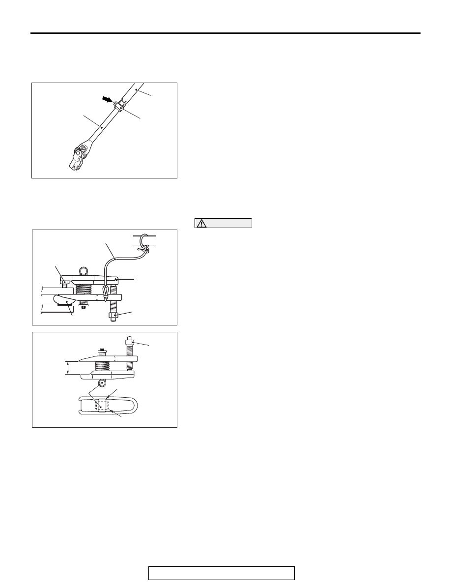
<<A>> STEERING COLUMN SHAFT ASSEMBLY 
CONNECTION DISCONNECTION

Disconnect the steering gear and linkage assembly from the 
steering column shaft assembly while sliding the shaft A to the 
shaft B with the clip claw as shown in the figure is pinched.

.

<<B>> SELF-LOCK NUT (TIE-ROD END AND 
KNUCKLE CONNECTION) REMOVAL

CAUTION

• Loosen the self-locking nut from the ball joint, but do 

not remove here. Use the special tool.

• To prevent the special tool from dropping off, suspend 

it with a cord.

1. Install the special tool MB991897or MB992011 as shown in 

the figure.

2. Turn the bolt and knob to make the special tool jaws parallel, 

then hand-tighten the bolt. After tightening, check that the 
jaws are still parallel.
NOTE: To adjust the special tool jaws to be parallel, set the 
knob as shown in the figure so that it functions as a fulcrum 
of the jaws.

3. Turn the bolt and disconnect the tie-rod end from the 

steering knuckle.

.

AC709235AB

Shaft B

Shaft A

Clip

Claw

AC702796 AB

Cord

Bolt

MB991897
or
MB992011

Nut

Ball joint

AC702797AB

Parallel

Knob

Bolt

Correct

Wrong

CROSSMEMBER

TSB Revision

POWER PLANT MOUNT

32-16

<<C>> FRONT AXLE CROSSMEMBER 
ASSEMBLY REMOVAL

1. Jack up and support the front axle crossmember assembly, 

and remove it.

2. Check the hoses and harnesses for roughness, and then 

remove the front axle crossmember assembly with the rear 
roll stopper and the steering gear and linkage assembly 
installed.

INSTALLATION SERVICE POINTS

.

>>A<< STABILIZER BAR/STABILIZER BUSH-
ING/STABILIZER BAR BRACKET INSTALLATION

Install the stabilizer bar, the stabilizer bushing and the stabilizer 
bar bracket as shown in the figure.

.

>>B<< JOINT COVER GROMMET INSTALLATION

Install the joint cover grommet to the steering gear and linkage 
assembly by aligning the mating marks as shown in the figure.

AC702798

Transmission jack

Piece of wood

AB

AC609899

AF

Stabilizer bushing

Front axle
crossmember

Stabilizer bush
bracket

Slit

Vehicle front side

AC700255AG

Steering gear
and linkage 
assembly

Joint cover grommet

CROSSMEMBER

TSB Revision

POWER PLANT MOUNT

32-17

REMOVAL AND INSTALLATION <3.0L ENGINE>

M1321003201725

CAUTION

• Before replacing the steering wheel assembly and driver's air bag module assembly, always refer 

to GROUP 52B, Service Precautions 

P.52B-25

and Air Bag Module(s) and Clock Spring 

P.52B-439

.Also, position the front wheels in a straight ahead direction, and remove the ignition 

key. If you fail to do this, clock spring for SRS may get damage, making the SRS (air bag) inopera-
tive, and it may cause a serious injury to the driver.

• The parts indicated by * are the bolts/nuts with friction coefficient stabilizer. In removal, ensure 

there is no damage, clean dust and soiling from the bearing and thread surfaces, and tighten them 
to the specified torque.

• After installation, perform calibration to make ASC-ECU learn the neutral position of the steering 

wheel sensor. (Refer to GROUP 35C, On-vehicle Service 

 Steering Wheel Sensor Calibration 

P.35C-285

).

Pre-removal operation
• Steering Wheel Air Bag Module Assembly Removal 

(Refer to GROUP 37, Steering Wheel 

P.37-32

).

• Footrest Removal.

• Front Exhaust Pipe Removal (Refer to GROUP 15, 

Exhaust Pipe and Main Muffler 

P.15-24

).

• Front Roll Stopper and Centermember Assembly 

Removal (Refer to 

P.32-11

).

• Power Steering Fluid Drain (Refer to GROUP 37, 

On-vehicle Service 

− Fluid Replacement 

P.37-25

).

• Engine Room Under Cover Front and Engine Room Side 

Cover Removal (Refer to GROUP 51, Under Cover 

P.51-23

).

• Lower Arm Assembly Removal (Refer to GROUP 33, 

Lower Arm 

P.33-15

).

Post-installation operation
• Using Your Fingers, Press The Tie-rod End Ball Joint Dust 

Cover To Check for a Crack or Damage (Refer to GROUP 

37, On-vehicle Service 

− Ball Joint Dust Cover Inspection 

P.37-23

).

• Using Your Fingers, Press The Stabilizer Link Ball Joint 

Dust Cover To Check for a Crack or Damage (Refer to 

GROUP 33, On-vehicle Service 

− Lower Arm Ball Joint 

Dust Cover Inspection 

P.33-9

).

• Lower Arm Assembly Installation (Refer to GROUP 33, 

Lower Arm 

P.33-15

).

• Front Roll Stopper and Centermember Assembly Installa-

tion (Refer to 

P.32-11

).

• Engine Room Under Cover Front and Engine Room Side 

Cover Installation (Refer to GROUP 51, Under Cover 

P.51-23

).

• Footrest Installation.

• Front Exhaust Pipe Installation (Refer to GROUP 15, 

Exhaust Pipe and Main Muffler 

P.15-24

).

• Clock Spring Centering (Refer to GROUP 52B, Air Bag 

Modules and Clock Spring 

P.52B-439

).

• Steering Wheel Air Bag Module Assembly Installation 

(Refer to GROUP 37, Steering Wheel 

P.37-32

).

• Power Steering Fluid Refilling and Bleeding (Refer to 

GROUP 37, On-vehicle Service 

− Fluid Replacement 

P.37-25

).

• Steering Wheel Straight-ahead Position Check.

• Front Wheel Alignment Check and Adjustment (Refer to 

GROUP 33, On-vehicle Service 

− Front Wheel Alignment 

Check and Adjustment 

P.33-7

).

CROSSMEMBER

TSB Revision

POWER PLANT MOUNT

32-18

Required Special Tool:

• MB991897 or MB992011: Ball Joint Remover

AC710004

1

2

N

25 ± 5 N·m
19 ± 3 ft-lb 

3

4

5

N

6

7

7

8

20 ± 5 N·m
15 ± 3 ft-lb 

9

9

10

11

12

13

12

13

14

15

39 ± 6 N·m
29 ± 4 ft-lb

57 ± 7 N·m
42 ± 5 ft-lb

70 ± 10 N·m
52 ± 7 ft-lb 

5.0 ± 2.0 N·m
45 ± 17 in-lb

31 ± 4 N·m
23 ± 3 ft-lb

31 ± 4 N·m
23 ± 3 ft-lb

50 ± 5 N·m
37 ± 3 ft-lb

50 ± 5 N·m
37 ± 3 ft-lb

39 ± 6 N·m
29 ± 4 ft-lb

AB

53 ± 8 N·m
40 ± 5 ft-lb

110 ± 11 N·m*
82 ± 8 ft-lb* 

2

<AWD>

<FWD>

53 ± 8 N·m
40 ± 5 ft-lb

Removal steps 

<<

A

>>

1.

Steering gear and joint connecting 
bolt

<<

B

>>

2.

Self-lock nut (Tie-rod end and 
knuckle connection)

3.

Stabilizer link assembly

4.

Pressure hose connection

5.

Gasket

6.

Return hose connection

7.

Rear roll stopper center bolt

<<

C

>>

Front axle crossmember assembly

>>

B

<< 8.

Joint cover grommet

9.

Rear roll stopper

10. Heat protector
11. Steering gear and linkage assembly

>>

A

<< 12. Stabilizer bar bracket

>>

A

<< 13. Stabilizer bushing

>>

A

<< 14. Stabilizer bar

15. Front axle crossmember

Removal steps (Continued)


Content   ..  541  542  543  544   ..