Mitsubishi Outlander GS45X. Manual - part 223
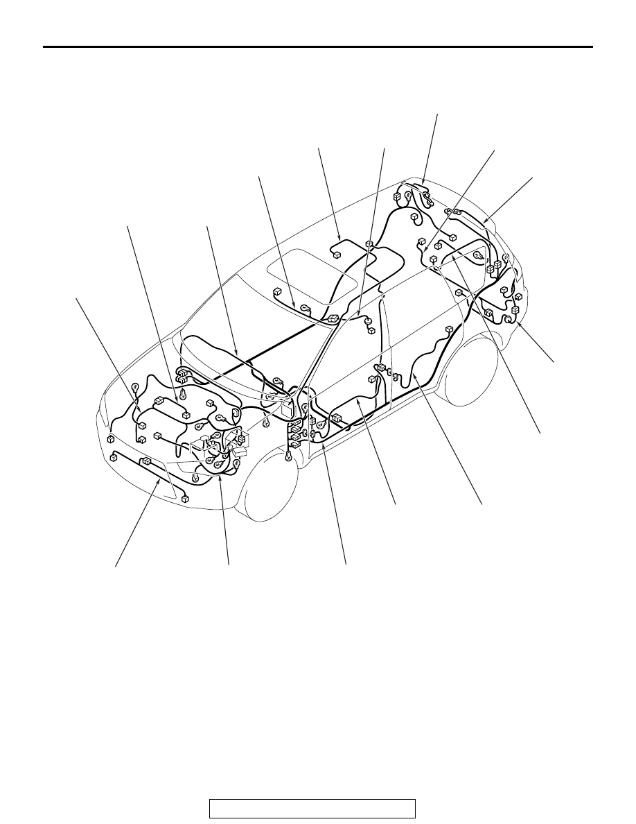
OVERALL CONFIGURATION DIAGRAM <3.0L ENGINE>
TSB Revision
CONFIGURATION DIAGRAMS
80A-3
OVERALL CONFIGURATION DIAGRAM <3.0L ENGINE>
M1801000103115
NOTE:
.
1. This illustration shows only major wiring harnesses.
2. *: also equipped at the right side.
AC900249
AD
Instrument panel
wiring harness
Control wiring
harness
Roof wiring
harness
Liftgate wiring
harness
Fog light
wiring harness
Injector wiring
harness
Front door
wiring harness
*
Rear door
wiring harness
*
Rear display
wiring harness
Fuel wiring
harness
Rear bumper
wiring harness
Rear end
wiring harness
Rear view camera
wiring harness
Front wiring
harness
Curtain air bag
wiring harness
*
Floor wiring
harness