Mitsubishi Outlander GS45X. Manual - part 1408


  Index      Mitsubishi     Mitsubishi Outlander GS45X - service repair manual


Search            


Content   ..  1406  1407  1408  1409   ..


Mitsubishi Outlander GS45X. Manual - part 1408


SRS AIR BAG DIAGNOSIS

TSB Revision

SUPPLEMENTAL RESTRAINT SYSTEM (SRS)

52B-127

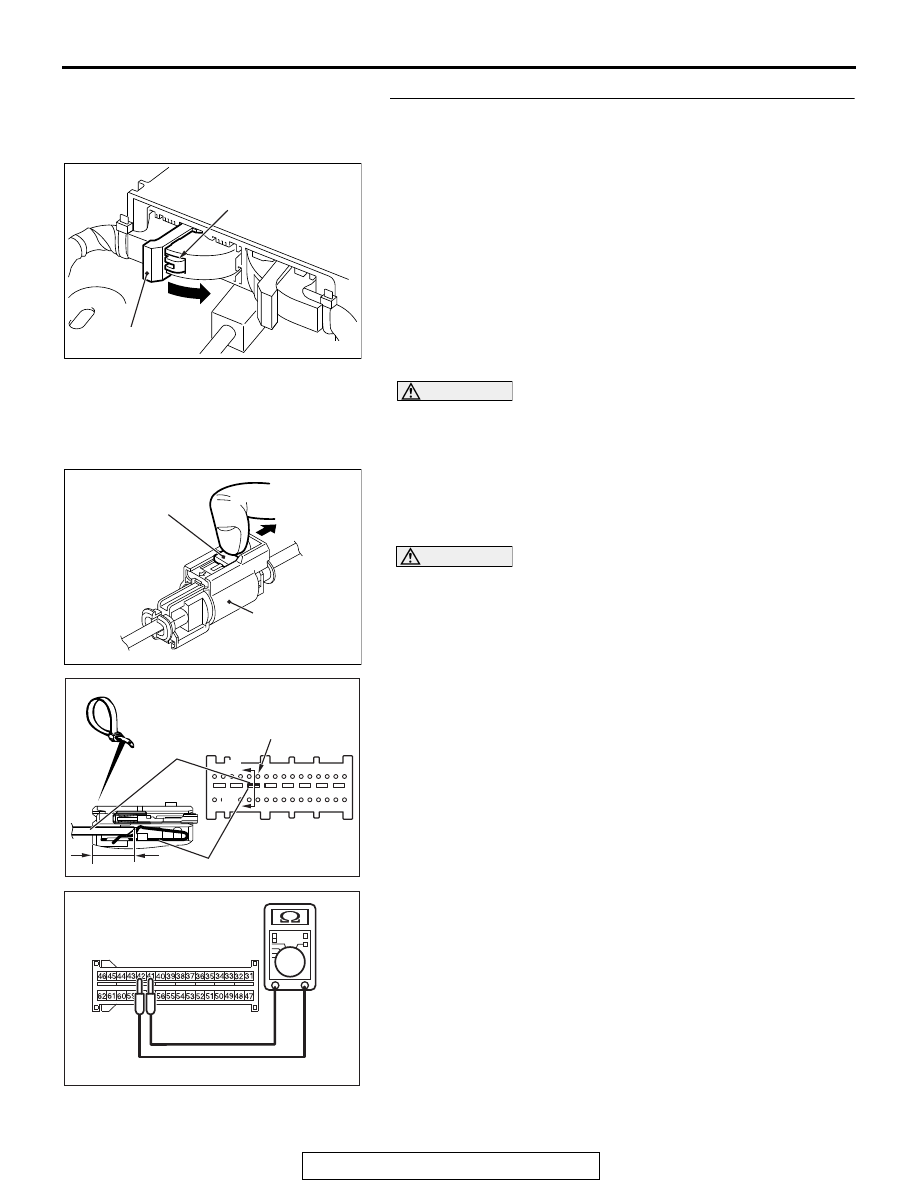
STEP 5. Resistance measurement at the C-27 SRS-ECU 
connector. 
(1) Disconnect the negative battery terminal.
(2) While pushing the part "A" indicated in the figure of the 

harness side connector, turn the lock lever to the direction 
of the arrow to release the lock lever, and disconnect the 
C-27 SRS-ECU connector.

DANGER

To prevent the air bag from deploying unintentionally, 
disconnect the intermediate connector D-13 to short 
the squib circuit.

(3) Disconnect the D-13 intermediate connector, unlock the 

connector by sliding the locking button to the direction of the 
arrow as shown in the figure, and then disconnect the 
connector.

CAUTION

The short spring may not be released due to the insuffi-
cient insertion. Therefore, insert the insulator for 4 mm (0.6 
inch) or more.

(4) Insert a cable tie [3 mm (0.12 inch) wide, 0.5 mm (0.02 inch) 

thick] between terminal 41, 42 and the short spring to 
release the short spring.

(5) Check for continuity between the C-27 wiring harness side 

connector terminal No. 41 and No. 42.
It should be open circuit.

Q: Is it open circuit?

YES : Go to Step 7.
NO :  Repair the wiring harness. 

AC506734

A

AB

Lock lever

AC706606

AH

Locking button

Intermediate 

connector

AC507303AI

A

A

C-27 Harness side
connector (front view)

Section
A - A

Cable tie

Short spring

4 mm or more

Terminal

AC701588

C-27 Harness side
connector (front view)

AB

SRS AIR BAG DIAGNOSIS

TSB Revision

SUPPLEMENTAL RESTRAINT SYSTEM (SRS)

52B-128

STEP 6. Short circuit check between the D-109 curtain air 
bag module harness side connector and the D-13 
intermediate harness.
(1) Disconnect the negative battery terminal.

DANGER

To prevent the air bag from deploying unintentionally, 
disconnect the curtain air bag module connector 
D-109 to short the squib circuit.

(2) Disconnect curtain air bag module (LH) D-109. Use a 

flat-tipped screwdriver to unlock the locking button at the 
harness side connector by withdrawing it toward you in two 
stages, and then disconnect the connector.

(3) Disconnect the D-13 intermediate connector, unlock the 

connector by sliding the locking button to the direction of the 
arrow as shown in the figure, and then disconnect the 
connector.

(4) Because the short spring is installed to the D-13 

intermediate connector (curtain air bag harness side), insert 
a cable tie [3 mm (0.12 inch) wide, 0.5 mm (0.02 inch) thick] 
between terminals 1, 2 and the short spring to release the 
short spring.

CAUTION

Do not insert a probe into the terminal from its front side 
directly, as the connector contact pressure may be weak-
ened.
(5) Check for continuity between the D-13 intermediate 

connector (curtain air bag harness side) terminal No. 1 and 
No. 2.
It should be open circuit.

Q: Is it open circuit?

YES : Replace the curtain air bag module (LH) (Refer to 

P.52B-453

). Then go to Step 7. 

NO :  Repair the wiring harness. 

AC701573

Locking 
button


Flat-tipped screwdriver

Inflator

Curtain air bag wiring
harness side connector


AB

AC706606

AH

Locking button

Intermediate 

connector

AC700119

D-13 Intermediate 
connector (module side ) 

22 mm or more

Cable tie

Short spring

AK

AC709326

D-13 Intermediate connector 
(Curtain air bag harness side)
(rear view)

AB

SRS AIR BAG DIAGNOSIS

TSB Revision

SUPPLEMENTAL RESTRAINT SYSTEM (SRS)

52B-129

STEP 7. Recheck for diagnostic trouble code. 
Check again if the DTC is set.
(1) Erase the DTC.
(2) Turn the ignition switch to the "ON" position.
(3) Check if the DTC is set.
(4) Turn the ignition switch to the "LOCK" (OFF) position.
Q: Is DTC B1B1B set?

YES : Replace SRS-ECU. (Refer to 

P.52B-436

.)

NO :  Intermittent Malfunction (Refer to GROUP 00, How to 

Use Troubleshooting/Inspection Service Points 

− How 

to Cope with Intermittent Malfunction 

P.00-15

).

ZC501967

AC404789

AC701411AB

MB991824

MB991827

MB991910

Data link 
connector

SRS AIR BAG DIAGNOSIS

TSB Revision

SUPPLEMENTAL RESTRAINT SYSTEM (SRS)

52B-130

DTC B1B20: Curtain Air Bag Module (RH) (Squib) System (Shorted to Squib Circuit Ground)

CAUTION

If DTC B1B20 is set in the SRS-ECU, always diag-
nose the CAN main bus line.

.

CIRCUIT OPERATION

• The SRS-ECU judges how severe a collision is 

by detecting signals from the side impact sensors 
installed on the lower side of the center pillar and 
at the quarter panel inner. If the impact is over a 
predetermined level, the SRS-ECU sends an 
ignition signal. At this time, if the side collision 
safing G-sensor is on, the SRS air bag will inflate. 

• The ignition signal is input to the curtain air bag 

module (RH) to inflate the curtain air bag.

AC709517

CURTAIN AIR BAG
MODULE
(SQUIB) (RH)

: CONNECTOR LOCK SWITCH
  CONNECTOR COUPLED: ON
  CONNECTOR UNCOUPLED: OFF

NOTE

SRS-ECU

Curtain Air Bag Module (Squib) (RH) Circuit

AB

AC901076

C-27 (Y)

AC

Connector: C-27

AC901080AC

Connectors: D-08, D-104

D-104 (B)

D-08 (Y)


Content   ..  1406  1407  1408  1409   ..