Mitsubishi Outlander GS45X. Manual - part 1363


  Index      Mitsubishi     Mitsubishi Outlander GS45X - service repair manual


Search            


Content   ..  1361  1362  1363  1364   ..


Mitsubishi Outlander GS45X. Manual - part 1363


WINDSHIELD WIPER AND WASHER

TSB Revision

EXTERIOR

51-75

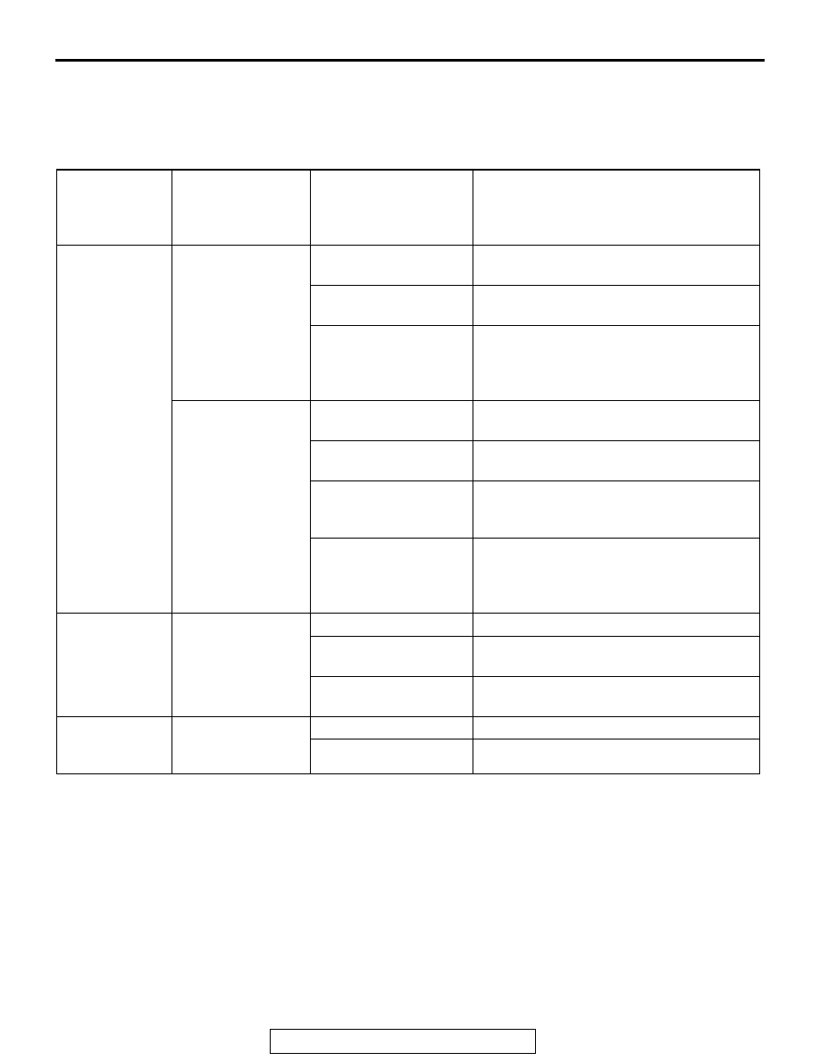
CONFIGURATION FUNCTION

M1511027402031

Using the ETACS system of scan tool MB991958, 
the following functions can be programmed. The pro-
grammed information is held even when the battery 
is disconnected.

Adjustment 
item (scan tool 
MB991958 
display)

Adjustment item

Adjusting contents 
(scan tool MB991958 
display)

Adjusting contents

Front wiper 
operation

Adjustment of the 
intermittent 
windshield wiper 
operation <vehicles 
without auto light>

Normal INT

Intermittent wiper interval is fixed to 4 
seconds.

Variable INT

Intermittent wiper interval is calculated only 
by the wiper volume control.

Speed Sensitive

Intermittent wiper interval is calculated 
according to the intermittent wiper volume 
control and vehicle speed (initial 
condition).

Adjustment of the 
intermittent 
windshield wiper 
operation <vehicles 
with auto light>

Normal INT

Intermittent wiper interval is fixed to 4 
seconds.

Variable INT

Intermittent wiper interval is calculated only 
by the wiper volume control.

Speed Sensitive

Intermittent wiper interval is calculated 
according to the intermittent wiper volume 
control and vehicle speed.

Rain Sensitive

Intermittent wiper interval is calculated 
according to the intermittent wiper volume 
control and lighting control sensor (initial 
condition).

Front wiper 
washer

Disabling or 
enabling 
washer-linked wiper 
function

Only Washer

No function

Washer & Wiper

With function: Without delayed finishing 
wipe function (Initial condition)

With after wipe

With function: With delayed finishing wipe 
function

Intelligent 
washer

With/without 
intelligent washer 
function

Disable

No function

Enable

With function (initial condition)

WINDSHIELD WIPER AND WASHER

TSB Revision

EXTERIOR

51-76

WINDSHIELD WIPER

REMOVAL AND INSTALLATION

M1511007901398

Required Special Tool:

• MB991955: M.U.T.-III sub-assembly

• MB991223: Harness set

AC808972

Section B – B

Section C – C

A

B

C

5

2

5

(LH)

5

(LH)

5

(RH)

5

(RH)

8

NOTE
        : Clip positions     

: Claw positions

1

3

4

4

B

8

7

7

5

6

6

D

N

View D

Specified grease: Multipurpose
grease SAE J310, NLGI No.1
(mineral oil + Li) or equivalent

View A

Clip

Claw

8.0 ± 2.0 N·m
71 ± 18 in-lb

8.0 ± 2.0 N·m
71 ± 18 in-lb

8.0 ± 2.0 N·m
71 ± 18 in-lb

27 ± 3 N·m
20 ± 2 ft-lb

C

AC

Wiper blade removal steps 

1.

Wiper blade assembly

>>C<<

2.

Wiper blade
Windshield wiper motor and link 
assembly removal steps 

>>B<<

3.

Wiper arm and blade assembly

4.

Hood weatherstrip rear

5.

Front deck garnish

6.

Windshield wiper link

7.

Wiper motor link plate

<<A>>

>>A<<

8.

Windshield wiper motor

Windshield wiper motor and link 
assembly removal steps 

WINDSHIELD WIPER AND WASHER

TSB Revision

EXTERIOR

51-77

NOTE: For removal and installation of the wiper and 
washer switch, refer to GROUP 54A, Column switch 

P.54A-323

.

REMOVAL SERVICE POINT

.

<<A>> WINDSHIELD WIPER MOTOR REMOVAL

1. Remove the wiper link rod joint from the wiper motor link 

plate.

2. Connect the wiper motor to a battery, and rotate the link 

plate as shown.

3. In this position, withdraw the link plate from the wiper link 

assembly.

AC511723AC

Wiper motor 
link plate

AC511724

4

5

3

1

2

4

5

3

1

2

AB

Wiper motor

<Link plate disconnected>

<Link plate rotated>

WINDSHIELD WIPER AND WASHER

TSB Revision

EXTERIOR

51-78

INSTALLATION SERVICE POINT

.

>>A<< WINDSHIELD WIPER MOTOR INSTALLA-
TION

1. Position the wiper motor link plate as shown, and assemble 

it to the wiper link assembly.
NOTE: 

.

The link plate can be assembled to the wiper link assem-
bly only at this position. If not, rotate the link plate to this 
position (Refer to Stop Position Check, 

P.51-79

).

Wiper motor replacement parts are supplied with the link 
plate positioned as shown.

2. Connect the assembled wiper motor to a battery, and set it 

to the automatic stop position (Refer to Stop Position Check, 

P.51-79

).

3. Apply grease to the inside of link rod joint (as required) and 

connect the link rod to wiper motor link plate.

.

>>B<< WIPER ARM AND BLADE ASSEMBLY 
INSTALLATION

Install the wiper arm and blade assembly at the specified posi-
tions.

(A): 

φ 2 marking ± 5 mm(0.20 in)

.

AC511725AB

Wiper motor link plate

AC702508

AD

A

A

A

A

Ø2 marking

Ø2 marking

5(0.20)

5(0.20)

Ø2marking

Section A – A

Unit: mm (in)

Front deck garnish


Content   ..  1361  1362  1363  1364   ..