Content .. 1292 1293 1294 1295 ..
Mitsubishi Outlander GS45X. Manual - part 1294
DIAGNOSIS
TSB Revision
CONTROLLER AREA NETWORK (CAN)
54C-121
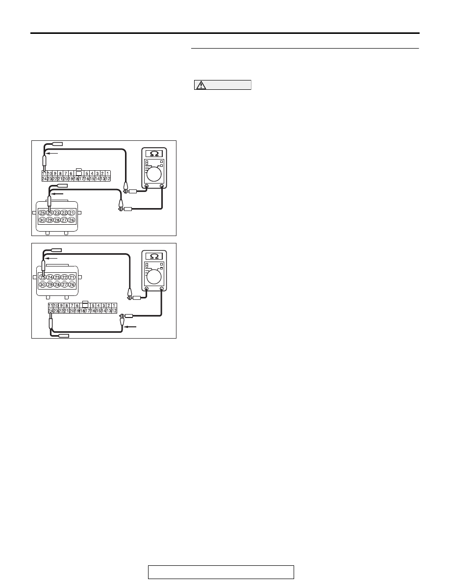
STEP 2. Check the wiring harness between joint connector
(CAN1) C-103 and occupant classification-ECU connector
D-34-2 for open circuit.
CAUTION
Strictly observe the specified wiring harness repair proce-
dure. For details refer to
(1) Disconnect joint connector (CAN1) C-103 and occupant
classification-ECU connector D-34-2, and check the wiring
harness.
(2) Check the wiring harness between joint connector (CAN1)
C-103 (terminal No.11) and occupant classification-ECU
connector D-34-2 (terminal No.24)
OK: Continuity exists (2 ohms or less)
(3) Check the wiring harness between joint connector (CAN1)
C-103 (terminal No.24) and occupant classification-ECU
connector D-34-2 (terminal No.25)
OK: Continuity exists (2 ohms or less)
Q: Is the wiring harness between joint connector (CAN1)
C-103 and occupant classification-ECU connector
D-34-2 in good condition?
YES : Check the power supply circuit of the occupant
classification-ECU. Refer to GROUP 52B, SRS air
bag Diagnosis
.
NO : Repair the wiring harness between joint connector
(CAN1) C-103 and occupant classification-ECU
connector D-34-2.
AC709707
AC709707 ME
Harness side: C-103
Harness side: D-34-2
Test harness
Test harness
AC709707 MF
Harness side: C-103
Harness side: D-34-2
Test harness
Test
harness