Mitsubishi Outlander GS45X. Manual - part 1244


  Index      Mitsubishi     Mitsubishi Outlander GS45X - service repair manual


Search            


Content   ..  1242  1243  1244  1245   ..


Mitsubishi Outlander GS45X. Manual - part 1244


CYLINDER HEAD AND VALVES

TSB Revision

ENGINE OVERHAUL <2.4L ENGINE>

11B-51

INSTALLATION SERVICE POINTS

.

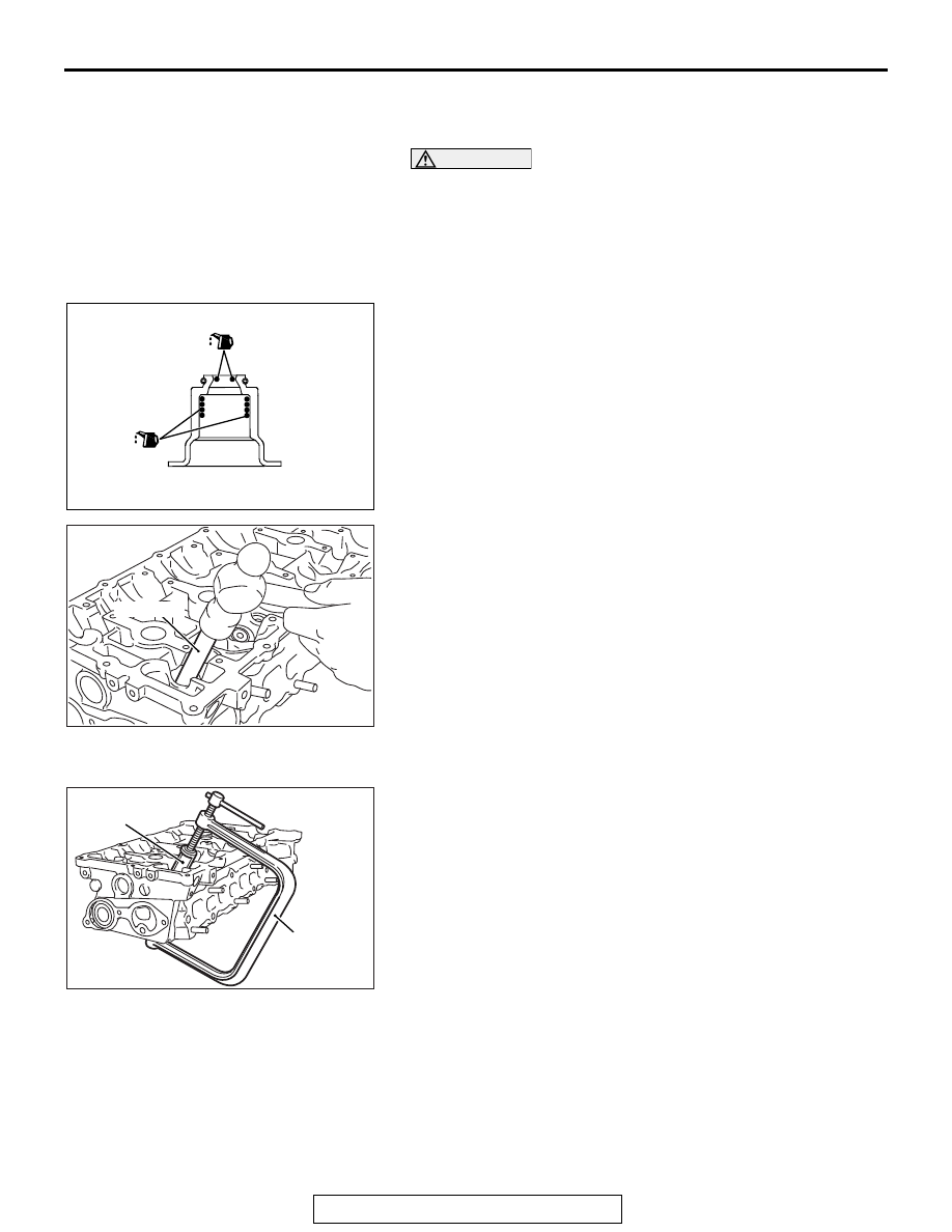
>>A<< VALVE STEM SEAL INSTALLATION

CAUTION

• The valve stem seal must not be reused.
• Do not damage the tappet wall during assembly.
• Be sure to use a special tool to install the valve stem 

seal. Poor installation causes oil loss via valve guides.

• If oil is not applied, the valve stem seal may rise to the 

surface after it is press fitted.

1. Apply a thin coat of engine oil to a new valve stem seal.

2. Use special tool MD998737 to press fit the valve stem seal 

into the valve guide with the valve stem used as a guide.

.

>>B<< RETAINER LOCK INSTALLATION

Use a special tool MD998735, and MB992089 to compress the 
valve spring and to install the retainer lock.

.

AK503378 AE

AK502742AD

MD998737

AK502741AD

MB992089

MD998735

CYLINDER HEAD AND VALVES

TSB Revision

ENGINE OVERHAUL <2.4L ENGINE>

11B-52

>>C<< CYLINDER HEAD GASKET / CYLINDER 
HEAD ASSEMBLY INSTALLATION

1. Completely remove the liquid gasket on the upper plane of 

the cylinder block and the lower plane of the cylinder head.

CAUTION

Sufficiently check that there is no residual oil on the place 
where degreasing is performed. If fingerprints are left, do 
not touch it with bare hands after the degreasing, since the 
oils from your fingers will harm the seal ability.
2. Degrease the place specified in the illustration.

3. As shown in the illustration, apply a 2.5 

± 0.5 mm (0.1 ± 0.02 

inch) of sealant to the top face of cylinder block.

Specified sealant:

Three bond 1217G or exact equivalent

4. Install the cylinder head gasket.

NOTE: Check that the center of the liquid gasket is located 
toward the cylinder gasket in the position specified in the 
illustration.

5. As shown in the illustration, apply a 2.5 

± 0.5 mm (0.1 ± 0.02 

inch) of sealant to the top face of cylinder head gasket.

Specified sealant:

Three bond 1217G or exact equivalent

6. Install the cylinder head assembly.

.

AK602902AE

Top face of cylinder block 

Degrease

Degrease

Bottom face of cylinder head 

AK602942AD

Ø2 to Ø3 mm
(0.079 to 0.118 in)

Timing chain side

CYLINDER HEAD AND VALVES

TSB Revision

ENGINE OVERHAUL <2.4L ENGINE>

11B-53

>>D<< CYLINDER HEAD BOLT INSTALLATION

1. Install new cylinder head bolts and washers in the following 

procedure.
NOTE:  Cylinder head bolts and washers must not be 
reused.

2. Apply an appropriate amount of engine oil to top and bottom 

surfaces of washers and threaded portion of bolts.

3. Install cylinder head bolts to the cylinder head.

NOTE: Bolts and washers are different parts for bolts on the 
timing chain side.

4. Tighten cylinder head bolts in several steps to the specified 

tightening torque of 35 

± 2 N⋅m (26 ± 1 ft-lb) according to the 

assembly order.

5. Put a paint mark on all of cylinder head bolt heads and 

cylinder head.

CAUTION

• When the tightening angle is smaller than the specified 

tightening angle, the appropriate tightening capacity 
cannot be secured.

• When the tightening angle is larger than the specified 

tightening angle, remove the bolt to start from the 
beginning again according to the procedure.

6. Tighten the cylinder head 90

° according to the tightening 

order.
Tighten it further 90

° and make sure that the paint mark on 

the cylinder head bolt is in a straight line with that on the 
cylinder head.

INSPECTION

M1113007002545

.

CYLINDER HEAD

1. Check the cylinder head for water leakage, gas leakage, 

damage or cracks before cleaning.

2. Completely remove oil, scale, sealant, carbon, etc. After 

cleaning oil passages, blow air to make sure that they are 
not clogged.

AK502392

8

10

9

7

3

5

1

2

6

4

AD

Timing chain side

AK502523AD

Paint mark

Paint mark

90˚

90˚

Paint mark

Paint mark

CYLINDER HEAD AND VALVES

TSB Revision

ENGINE OVERHAUL <2.4L ENGINE>

11B-54

CAUTION

The grinding limit shall be within 0.2 mm (0.008 inch) in 
combination with the cylinder block to be assembled.
3. For the flatness on the cylinder head bottom, measure 

distortion using a straight edge and free gauge. If the 
distortion exceeds the limit, grind and repair it.

Distortion on bottom

Standard value: Within 0.05 mm (0.002 inch)
Limit: 0.2 mm (0.08 inch)
Grinding limit: 0.2 mm (0.008 inch)

Cylinder head height

Standard value: 128.5 mm (5.06 inch)

.

VALVE

1. Repair the valve seat if contact with the valve seat is poor, 

uneven or broken.

2. Measure the margin.

If the limit is exceeded, replace the valve.

Standard value:

Intake 1.022 mm (0.0402 inch)
Exhaust 1.094 mm (0.0431 inch)

Limit:

Intake 0.522 mm (0.0206 inch)
Exhaust 0.594 mm (0.0234 inch)

3. Measure overall length of the valve.

If the limit is exceeded, replace the valve.

Standard value:

Intake 113.18 mm (4.456 inch)
Exhaust 105.89 mm (4.169 inch)

Limit:

Intake 112.68 mm (4.436 inch)
Exhaust 105.39 mm (4.149 inch)

.

VALVE SPRING

1. Measure free height of the spring.

If the limit is exceeded, replace the spring.

Standard value: 47.20 mm (1.858 inch)

2. Measure squareness of the spring.

If the inclination exceeds the limit, replace the spring.

Standard value: 2

° or less

Limit: 4

°

.

AK502740

AK305408AD

Margin

The bottom of valve
seat contact facet

AK305409AD

Length

AK305410AD

Free height

Squareness


Content   ..  1242  1243  1244  1245   ..