Mitsubishi Outlander GS45X. Manual - part 80
COLUMN SWITCH
TSB Revision
CHASSIS ELECTRICAL
54A-317
COLUMN SWITCH
GENERAL INFORMATION
M1543101800028
The column switch has a built in feature to ensure
the driver's safety during frontal collision of vehicle.
.
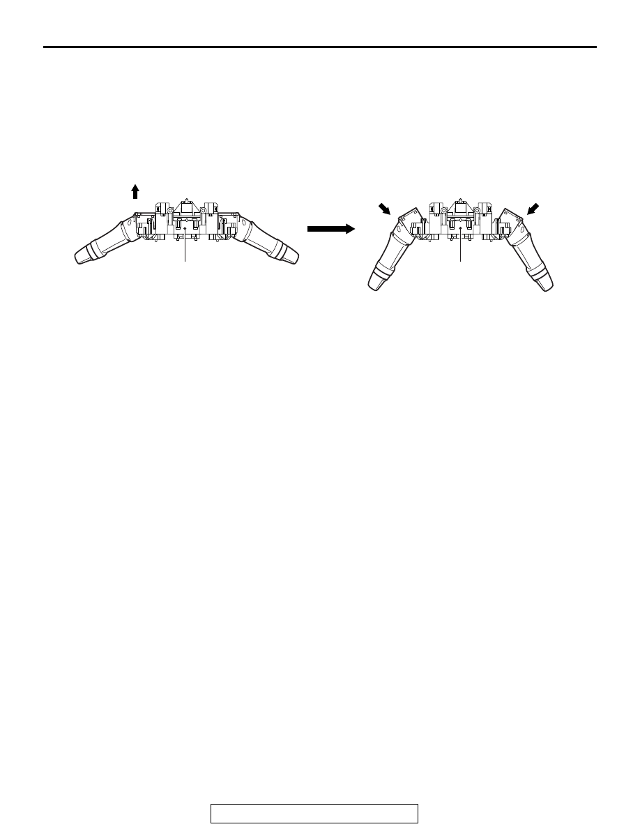
Function
If the column switch is moved toward the front of the
vehicle and hit on the instrument panel or meter
bezel during a frontal collision, the steering wheel is
moved to the front of the vehicle because the right
and left levers fall down, ensuring the driver's safety.
In addition, the column switch secures the rigidity
that the levers do not fall down by the normal opera-
tion. The column switch cannot be reused after the
deformation.
AC603959 AB
Collision load
Collision load
Column switch
Column switch
Front of vehicle