Mitsubishi Outlander GS45X. Manual - part 77
HAZARD WARNING LIGHT SWITCH
TSB Revision
CHASSIS ELECTRICAL
54A-305
DIAGNOSIS
STANDARD FLOW OF DIAGNOSTIC TROUBLESHOOTING
M1541501400152
Refer to GROUP 00
− Contents of troubleshooting
.
DIAGNOSTIC FUNCTION
M1541500600108
HOW TO CONNECT THE SCAN TOOL (M.U.T.-III)
Required Special Tools:
• MB991958: Scan Tool (M.U.T.-III Sub Assembly)
• MB991824: Vehicle Communication Interface (V.C.I.)
• MB991827: M.U.T.-III USB Cable
• MB991910: M.U.T.-III Main Harness A (Vehicles with
CAN communication system)
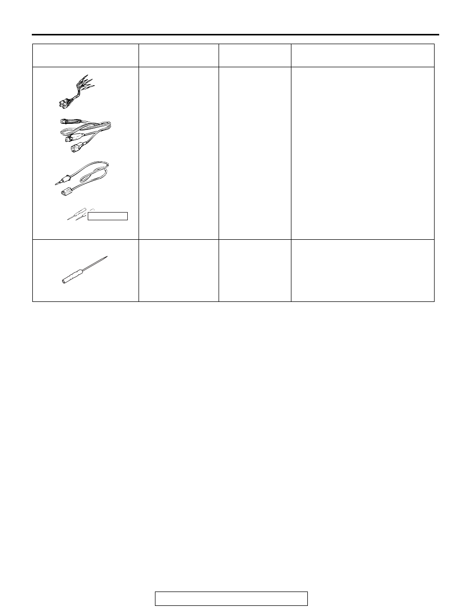
MB991223
a. MB991219
b. MB991220
c. MB991221
d. MB991222
Harness set
a. Check harness
b. LED harness
c. LED harness
adapter
d. Probe
General service
tool (jumper)
Continuity check and voltage
measurement at harness wire or
connector
a. Connector pin contact pressure
inspection
b. Power circuit inspection
c. Power circuit inspection
d. Commercial tester connection
MB992006
Extra fine probe
−
Continuity check and voltage
measurement at harness wire or
connector
Tool
Tool number and
name
Supersession
Application
MB991223
a
d
c
b
DO NOT USE
BA
MB992006