Mitsubishi Outlander GS45X. Manual - part 63


  Index      Mitsubishi     Mitsubishi Outlander GS45X - service repair manual


Search            


Content   ..  61  62  63  64   ..


Mitsubishi Outlander GS45X. Manual - part 63


REAR COMBINATION LIGHT

TSB Revision

CHASSIS ELECTRICAL

54A-249

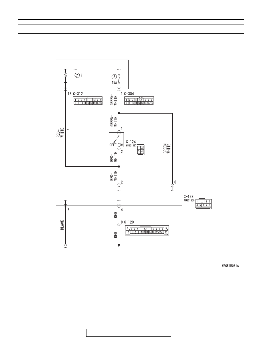
Inspection Procedure 3: Stoplight does not illuminate or go out normally.

ETACS-
ECU

Stoplight Circuit

STOP LAMP 
RELAY

STOPLIGHT 
SWITCH

·

STOP LIGHT

·HIGH-MOUNTED STOP LIGHT

REAR COMBINATION LIGHT

TSB Revision

CHASSIS ELECTRICAL

54A-250

.

COMMENTS ON TROUBLE SYMPTOM

If the stoplights do not illuminate or go out normally, 
the stoplight relay power supply, ground circuit sys-
tem, stoplight switch, or the stoplight relay 

*

 may be 

defective.
NOTE: 

*

: The stoplight relay cannot be inspected 

because it is a semiconductor relay.

.

PROBABLE CAUSES

• Malfunction of stoplight switch

• Malfunction of stoplight relay

• Damaged harness wires and connectors

DIAGNOSIS

Required Special Tools:

• MB992006: Extra fine probe

• MB991223: Harness set

STEP 1. Check stoplight relay connector C-133 for loose, 
corroded or damaged terminals, or terminals pushed back 
in the connector.
Q: Is stoplight relay connector C-133 in good condition?

YES : Go to Step 2.
NO :  Repair the damaged parts

STEP 2. Resistance measurement at stoplight relay 
connector C-133.
(1) Disconnect the connector, and measure at the wiring 

harness side.

(2) Measure the resistance between stoplight relay connector 

C-133 (terminal No. 8) and the body ground.

The measured value should be continuity exists (2 
Ω or less).

Q: Does the measured resistance value correspond with 

this range?
YES : 
Go to Step 4.
NO :  Go to Step 3.

AC901075BD

Connector: C-133

ACA02655AY

Connectors: C-304, C-312

C-304

C-312

AC702818 DL

 Harness side: C-133

REAR COMBINATION LIGHT

TSB Revision

CHASSIS ELECTRICAL

54A-251

STEP 3. Check the wiring harness between stoplight relay 
connector C-133 (terminal No. 8) and ground.
Check the ground line for open circuit.
Q: Is the wiring harness between stoplight relay connector 

C-133 (terminal No. 8) and ground in good condition?
YES : 
Go to Step 4.
NO :  Repair the wiring harness.

STEP 4. Check the stoplight switch.
Remove the stoplight switch.

• Check for continuity between the terminals of the switch.

Q: Is the stoplight switch in good condition?

YES : Go to Step 5.
NO :  Replace the stoplight switch.

Check 
condition

Terminal 
connector of 
tester

Normal 
condition

At free position 1 

− 2 (for 

stoplight switch)

Continuity 
exists


(2 

Ω or less)

− 4 (for cruise 

control)

No continuity

Press the 
plunger from the 
edge of the 
outer case by 
the dimension 
shown in the 
figure.

− 2 (for 

stoplight switch)

No continuity

− 4 (for cruise 

control)

Continuity 
exists


(2 

Ω or less)

REAR COMBINATION LIGHT

TSB Revision

CHASSIS ELECTRICAL

54A-252

STEP 5. Check the battery power supply circuit to the 
stoplight relay. Measure the voltage at stoplight relay 
connector C-133.
(1) Disconnect stoplight relay connector C-133 measure the 

voltage available at the wiring harness side of the 
connector.

(2) Measure the voltage between stoplight relay connector 

C-133 terminal 6 and ground.

• The voltage should measure approximately 12 volts 

(battery positive voltage).

(3) Stoplight switch: ON

(4) Measure the voltage between stoplight relay connector 

terminal No. 2 and the body ground.

• The voltage should measure approximately 12 volts 

(battery positive voltage).

Q: Is the measured voltage approximately 12 volts (battery 

positive voltage)?
YES : 
Go to Step 7.
NO :  Go to Step 6.

STEP 6. Check ETACS-ECU connector C-304 for loose, 
corroded or damaged terminals, or terminals pushed back 
in the connector.
Q: Is ETACS-ECU connector C-304 in good condition?

YES : Go to Step 7.
NO :  Repair the damaged parts

STEP 7. Check the wiring harness between stoplight relay 
connector C-133 (terminal No. 2/6) and ETACS-ECU 
connector C-304 (terminal No. 1).

• Check the power supply line (battery supply) for open circuit 

and short circuit.

Q: Is the wiring harness between stoplight relay connector 

C-133 (terminal No. 2/6) and ETACS-ECU connector 
C-304 (terminal No. 1) in good condition?
YES : 
Go to Step 8.
NO :  Repair the wiring harness.

AC608254EV

 Harness side: C-133

AC608254EW

 Harness side: C-133


Content   ..  61  62  63  64   ..