Mitsubishi Outlander GS45X. Manual - part 7
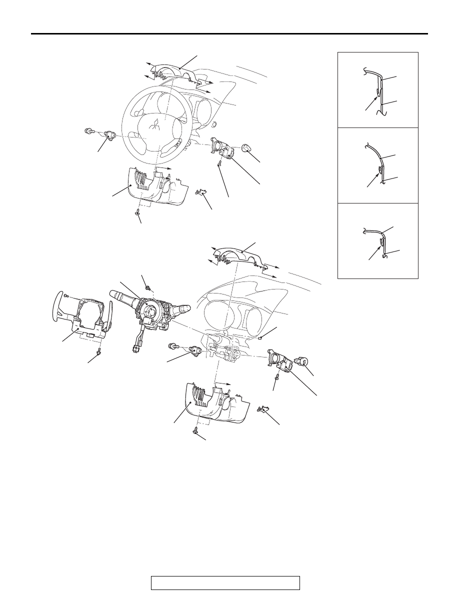
IGNITION SWITCH
TSB Revision
CHASSIS ELECTRICAL
54A-25
AC708537
AC801751
AC706806
Section A-A
Section C-C
Section B-B
4
3
4
3
4
3
3
6
6
2
4
4
5
7
10
5
AI
1
3
2
9
8
B
B
C
C
A
A
B
B
C
C
A
A
NOTE:
Claw position is symmetrical
<Vehicles with KOS>
<Vehicles with WCM>
Claw
Claw
Claw
2.0 ± 0.5 N·m
18 ± 4 in-lb
2.0 ± 0.5 N·m
18 ± 4 in-lb
7.0 ± 3.0 N·m
62 ± 27 in-lb
2.5 ± 0.5 N·m
23 ± 4 in-lb
2.5 ± 0.5 N·m
23 ± 4 in-lb
2.5 ± 0.5 N·m
23 ± 4 in-lb
Removal Steps
1.
IG knob cap <Vehicles with KOS>
2.
Ignition key cover
3.
Steering column lower cover
4.
Steering column upper cover
5.
Ignition switch
>>
A
<<
6.
Wireless control module (WCM)
<Vehicles with WCM>/Receiver
antenna module <Vehicles with
KOS>
7.
Key illumination bulb <Vehicles with
WCM and paddle shift>
8.
Paddle shift assembly <Vehicles
with WCM and paddle shift>
9.
Column switch assembly <Vehicles
with WCM>
<
<
A
>
>
10. Steering lock cylinder <Vehicles
with WCM>
Removal Steps (Continued)