Mitsubishi Outlander (2013+). Manual - part 338


  Index      Mitsubishi     Mitsubishi Outlander - service repair manual 2013 year


Search            


Content   ..  336  337  338  339   ..


Mitsubishi Outlander (2013+). Manual - part 338


WATER HOSE AND WATER PIPE

ENGINE COOLING

14-18

Specified sealant: ThreeBond 1324N or 
equivalent

NOTE: Install the engine coolant temperature 
sensor immediately after applying sealant.

CAUTION

After the installation, until a sufficient period of 
time (one hour or more) elapses, do not apply the 
oil or water to the sealant application area or 
start the engine.

AC509216

MB992042

AB

2. Use special tool water temp sensor wrench 

(MB992042) to tighten the engine coolant 
temperature sensor to the specified torque.

Tightening torque: 30 

± 9 Nm

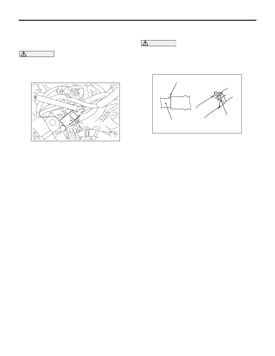
>>C<< RADIATOR UPPER HOSE/HOSE 
CLIP CONNECTION

CAUTION

Never reuse the hose clip whose claw is broken 
off to prevent the rusting.

1. Make mating mark on a new hose clip in the same 

position as the remove one.

AC606082

Water outlet fitting

AX

Protrusion

Mating marks

2. Insert the radiator upper hose until the protrusion 

of the water outlet fitting.

3. Align the mating marks on the radiator upper hose 

and hose clip.

4. Remove the hose clip claw and shorten the hose 

clip, then install the radiator upper hose.

INSPECTION

M1141003400876

WATER PIPE AND HOSE CHECK

Check the water pipe and hose for cracks, damage 
and clogs. Replace them if necessary.

RADIATOR

ENGINE COOLING

14-19

RADIATOR

REMOVAL AND INSTALLATION

M1141001503940

Pre-removal Operation
• Front under cover panel and front extension under cover 

panel removal (Refer to GROUP 51 

− Under Cover ).

• Engine coolant draining (Refer to 

P.14-9

).

• Air Cleaner assembly removal (Refer to GROUP 15 − Air 

Cleaner ) .

Post-installation Operation
• Air cleaner assembly installation (Refer to GROUP 15 − 

Air Cleaner ) .

• Engine coolant refilling (Refer to 

P.14-9

).

• Front under cover panel and front extension under cover 

panel installation (Refer to GROUP 51 

− Under Cover ).

ACB05949

3.4 ± 0.5 N·m

4.4 ± 0.5 N·m

5

6

10

3

12

19

20

1

16

14

22

21

23

26

25

7

AB

N

18

6.9 ± 1.0 N·m

21

8

19

17

11

2

13

N

N

N

4

9

N

3.4 ± 0.5 N·m

15

4.4 ± 0.5 N·m

27

10 ± 4 N·m

24

Removal steps 

1.

Radiator drain plug

2.

O-ring

3.

Radiator cap

4.

Radiator condenser tank hose

5.

Radiator condenser tank

6.

CVT fluid cooler feed hose

7.

CVT fluid cooler return hose

<<

A

>>

>>

A

<<

8.

Hose clip

<<

A

>>

>>

A

<<

9.

Radiator upper hose

10. Water pipe

Removal steps (Continued)

RADIATOR

ENGINE COOLING

14-20

REMOVAL SERVICE POINTS

<<A>> HOSE CLIP/RADIATOR HOSE 
REMOVAL

AC606081

Mating marks

AE

1. Make mating marks on the radiator hose and the 

hose clip as shown to install them in the original 
position.

AC302615

Hose clip

Claw (Tip)

AE

2. Break off the tip of hose clip claw and spread out 

the hose clip, then disconnect the radiator hose.

NOTE: If there is a hose clip claw, the hose clip 
cannot spread to capacity because the claw con-
tacts the hose clip.

INSTALLATION SERVICE POINTS

>>A<< RADIATOR HOSE/HOSE CLIP 
CONNECTION

CAUTION

Never reuse the hose clip whose claw is broken 
off to prevent the rusting.

1. Make mating mark on a new hose clip in the same 

position as the remove one.

AC606082

Protrusion

Pipe, fitting, or etc.

AU

Mating marks

2. Insert the radiator hose until the protrusion of the 

pipe.

3. Align the mating marks on the radiator hose and 

hose clip.

4. Remove the hose clip claw and shorten the hose 

clip, then install the radiator hose.

<<

A

>>

>>

A

<<

11. Hose clip

<<

A

>>

>>

A

<<

12. Radiator upper hose

<<

A

>>

>>

A

<<

13. Hose clip

<<

A

>>

>>

A

<<

14. Radiator lower hose
15. Water pipe

<<

A

>>

>>

A

<<

16. Hose clip

<<

A

>>

>>

A

<<

17. Radiator lower hose

Radiator fan motor connector 
connection

Condenser fan motor connector 
connection

18. Fan, fan motor and fan shroud 

assembly

Front end upper bar assembly 
(Refer to GROUP 42A 

− Loose 

Panel )

19. Support upper insulator

Condenser assembly (Refer to 
GROUP 55 

− Condenser 

Assembly 

20. Radiator assembly
21. Support lower insulator
22. Radiator fan
23. Radiator fan motor
24. Condenser fan
25. Condenser fan motor
26. Fan shroud
27. Radiator hose support

Removal steps (Continued)


Content   ..  336  337  338  339   ..