Mitsubishi Outlander (2003+). Manual - part 560
TROUBLESHOOTING
AUTOMATIC AIR CONDITIONER
55B-55
STEP 27. Check the wiring harness between
C-141 engine-ECU connector terminal No.78 and
C-26 A/C-ECU connector terminal No.32.
NOTE: Prior to the wiring harness inspection, check
intermediate connector C-104, and repair if
necessary.
•
Check the communication line for open circuit.
Q: Is the check result normal?
YES :
Go to Step 28.
NO :
Repair the wiring harness.
STEP 28. Check the wiring harness between
C-141 engine-ECU connector terminal No.69 and
C-26 A/C-ECU connector terminal No.34.
NOTE: Prior to the wiring harness inspection, check
intermediate connector C-104, and repair if
necessary.
•
Check the communication line for open circuit.
Q: Is the check result normal?
YES :
Replace the A/C-ECU or engine-ECU.
NO :
Repair the wiring harness.
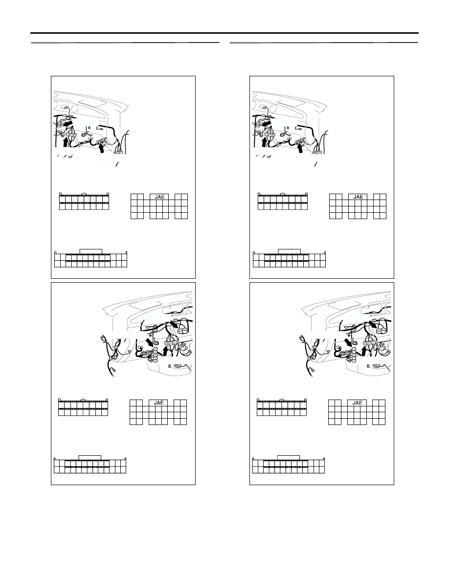
AC308719
Connectors: C-26, C-104, C-141 <LHD>
C-141
AQ
Harness side
C-141 (GR)
C-26 (B)
29
21
35
27
24
323130
22
23
33
25
34
26
36
28
C-26
Harness side
61
62
63
64
65
66
67
68
69
70
71
72
73
74
75
76
77
78
79
80
81
82
83
84
85
86
87
88
89
C-104 (B)
C-104
22
9
14
15
2 1
3
16
1918
5 4
17
6
21
7
20
8
25
12
10
23
11
24
26
13
JAE-E
AC308736
Connectors: C-26, C-104, C-141 <RHD>
C-141
AW
Harness side
C-141 (GR)
C-26 (B)
29
21
35
27
24
323130
22
23
33
25
34
26
36
28
C-26
Harness side
61
62
63
64
65
66
67
68
69
70
71
72
73
74
75
76
77
78
79
80
81
82
83
84
85
86
87
88
89
C-104 (B)
C-104
22
9
14
15
2 1
3
16
1918
5 4
17
6
21
7
20
8
25
12
10
23
11
24
26
13
JAE-E