Mitsubishi Outlander (2003+). Manual - part 456


  Index      Mitsubishi     Mitsubishi Outlander - service repair manual 2003 year


Search            


Content   ..  454  455  456  457   ..


Mitsubishi Outlander (2003+). Manual - part 456


SYMPTOM PROCEDURES

SMART WIRING SYSTEM (SWS) NOT USING SWS MONITOR

54B-113

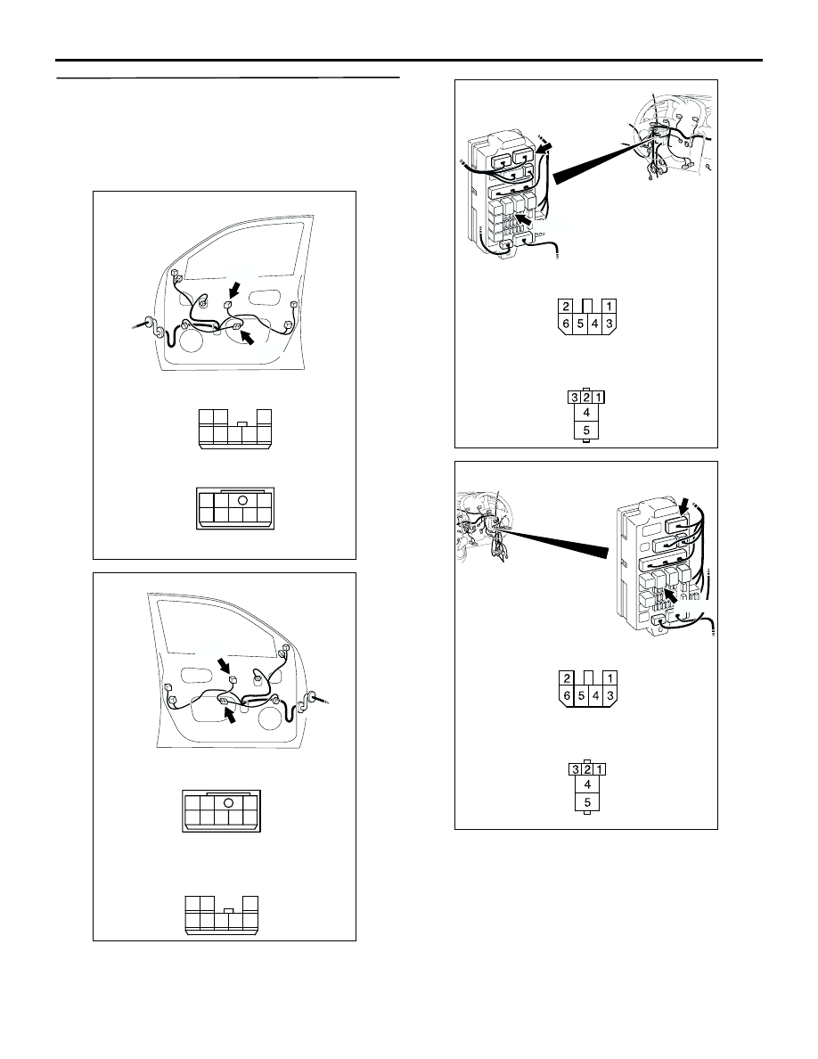
Step 8. Check the wiring harness from E-17 
power window sub switch (front RH) connector 
<L.H. drive vehicles> or E-31 power window sub 
switch (front LH) connector <R.H. drive vehicles> 
terminal No.4 to C-208 power window relay 
connector terminal No.4.

AC308794

Connectors: E-17, E-24 
<LHD>

AB

E-17

Harness side

E-24

E-17

E-24

1

4

5

3 2

7 6

8

4

1

5

2

7

6

8

3

AC308806

Connectors: E-30, E-31 
<RHD

AD

E-30

E-31

Harness side

E-30

E-31

1

4

5

3 2

7 6

8

4

1

5

2

7

6

8

3

AC308721

Junction block side

Junction block (Front view)

Connectors: C-203, C-208

C-203

C-208

Harness side

C-203

AG

<LHD>

C-208

AC308773

Junction block side

Junction block 
(front view)

Connectors: C-203, C-208

C-203

C-208

Harness side

C-203

AG

<RHD>

C-208

SYMPTOM PROCEDURES

SMART WIRING SYSTEM (SWS) NOT USING SWS MONITOR

54B-114

NOTE: 

Prior to the wiring harness inspection, check 
intermediate connectors C-15 <L.H. drive vehicles>, 
C-34<R.H. drive vehicles>, E-24 <L.H. drive 
vehicles> and E-30 <R.H. drive vehicles>, and 
junction block connector C-203, and repair if 
necessary.

Check the power supply line for open circuit.

Q: Is the check result normal?

YES : 

The trouble can be an intermittent 

malfunction (Refer to GROUP 00, How to 
Cope with Intermittent Malfunction 

P.00-6

).

NO : 

Repair the wiring harness.

Step 9. Connector check: E-23 power window 
motor (front RH) connector <L.H. drive vehicles> 
or E-13 power window motor (front LH) 
connector <R.H. drive vehicles>

Q: Is the check result normal?

YES : 

Go to Step 10.

NO : 

Repair the connector.

AC308718

Connector: C-15 <LHD>

AG

C-15(GR)

13

3

7

16

19

15

14

18

17

12

6

4

8

1

9

11

10

5

2

AC308735

Connector: C-34 
<RHD>

AI

C-34(GR)

13

3

7

16

19

15

14

18

17

12

6

4

8

1

9

11

10

5

2

AC308797

Connector: E-23

Harness side

E-23(GR)

AF

<LHD>

AC308805

Connector: E-13 
<RHD>

AG

Harness side

E-13(GR)

4

6 5

3 2 1

SYMPTOM PROCEDURES

SMART WIRING SYSTEM (SWS) NOT USING SWS MONITOR

54B-115

Step 10. Check the wiring harness from E-23 
power window motor (front RH) connector <L.H. 
drive vehicles> or E-13 power window motor 
(front LH) connector <R.H. drive vehicles> 
terminal Nos. 1 and 3 to E-17 <L.H. drive 
vehicles> power window sub switch (front LH) 
connector or E-31 <R.H. drive vehicles> power 
window sub switch (front RH) connector terminal 
Nos. 5 and 7.

NOTE: Prior to the wiring harness inspection, check 
intermediate connector E-24 <L.H. drive vehicles> or 
E-30 <R.H. drive vehicles>, and repair if necessary.

Check the input and output lines for open or short 
circuit.

Q: Is the check result normal?

YES : 

Go to Step 11.

NO : 

Repair the wiring harness.

Step 11. Retest the system.

After the power window sub switch (front RH) is 
replaced, check that the front passenger's door 
power window can be operated by the power window 
sub switch (front RH).
(1) Replace the power window sub switch (front RH).
(2) Check that the front passenger's door power 

window can be operated by the power window 
sub switch (front RH).

Q: Is the check result normal?

YES : 

The trouble can be an intermittent 

malfunction (Refer to GROUP 00 

 How to 

Cope with Intermittent Malfunction 

P.00-6

).

NO : 

Replace the power window motor assembly 
(front RH).

Step 12. Connector check: E-21 power window 
sub switch (rear RH) connector

Q: Is the check result normal?

YES : 

Go to Step 13.

NO : 

Repair the connector.

AC308794

Connectors: E-17, E-23, E-24 
<LHD>

AC

E-17

Harness side

E-23

E-24

Harness side

E-17

E-23(GR)

E-24

1

4

5

3 2

7 6

8

4

6 5

3 2 1

4

1

5

2

7

6

8

3

AC308806

Connectors: E-13, E-30, E-31 
<RHD>

AC

E-13

Harness side

E-30

E-31

Harness side

E-13

E-30

E-31

1

4

5

3 2

7 6

8

4

6 5

3 2 1

4

1

5

2

7

6

8

3

AC308795

Connector: E-21 

AC

Harness side

1

4

5

3 2

7 6

8

SYMPTOM PROCEDURES

SMART WIRING SYSTEM (SWS) NOT USING SWS MONITOR

54B-116

Step 13. Measure the resistance at E-21 power 
window sub switch (rear RH) connector.

(1) Disconnect the connector, and measure at the 

wiring harness side.

(2) Resistance between terminal 1 and body earth

OK: 2

 or less

Q: Is the check result normal?

YES : 

Go to Step 15.

NO : 

Go to Step 14.

Step 14. Check the wiring harness from E-21 
power window sub switch (rear RH) connector 
terminal No.1 to body earth.

NOTE: 

Prior to the wiring harness inspection, check 
intermediate connectors E-27 and D-02, and repair if 
necessary.

Check the earth wires for open circuit.

AC308795

Connector: E-21 

AC

Harness side

1

4

5

3 2

7 6

8

1

4

5

3 2

7 6

8

AC301472

Connector E-21
(Harness side)

AB

AC308796

Connectors: E-21, E-27

AB

E-21

E-27

E-21

E-27

Harness side

4

1

5

2

7

6

8

3

1

4

5

3 2

7 6

8

AC308781

Connector: D-02 
<LHD>

AE

8

3

1

4 5 6

2

7

AC308785

Connector: D-02 
<RHD>

AD

8

3

1

4 5 6

2

7


Content   ..  454  455  456  457   ..