Mitsubishi Outlander (2003+). Manual - part 451


  Index      Mitsubishi     Mitsubishi Outlander - service repair manual 2003 year


Search            


Content   ..  449  450  451  452   ..


Mitsubishi Outlander (2003+). Manual - part 451


SYMPTOM PROCEDURES

SMART WIRING SYSTEM (SWS) NOT USING SWS MONITOR

54B-93

Q: Is the check result normal?

YES : 

The trouble can be an intermittent 

malfunction (Refer to GROUP 00, How to 
Cope with Intermittent Malfunction 

P.00-6

).

NO : 

Repair the wiring harness.

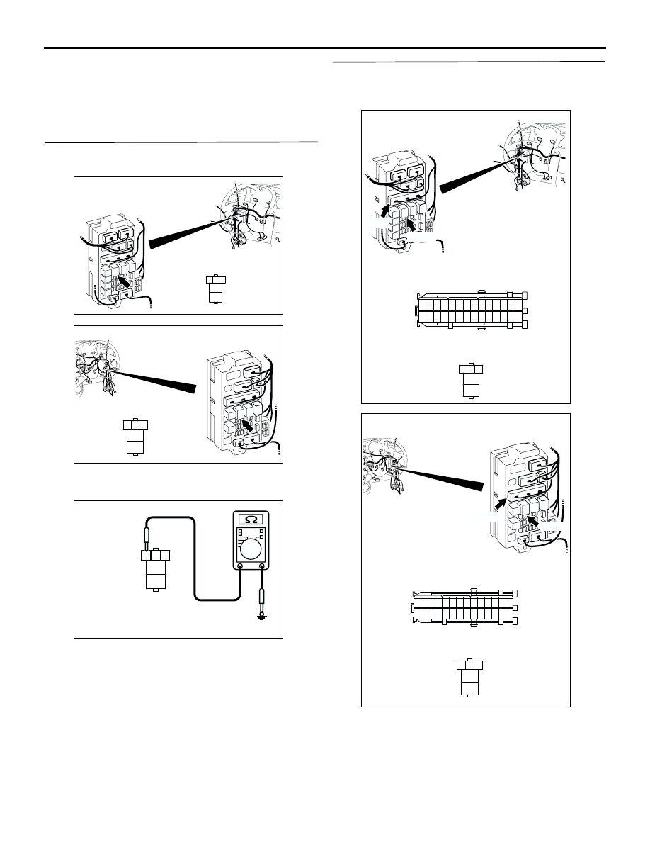
Step 9. Measure the resistance at C-208 power 
window relay connector.

(1) Disconnect the connector, and measure at the 

wiring harness side.

(2) Resistance between terminal 3 and body earth

OK: 2

 or less

Q: Is the check result normal?

YES : 

Go to Step 11.

NO : 

Go to Step 10.

Step 10. Check the wiring harness between C-208 
power window relay connector terminal No.3 and 
body earth.

NOTE: Prior to the wiring harness inspection, check 
junction block connector C-205, and repair if 
necessary.

Check the earth wires for open circuit.

AC308720

Connector: C-208

AG

3

4

5

1

2

Junction block (Front view)

Junction block side

<LHD>

AC308772

Connector: C-208

AF

3

4

5

1

2

Junction block (Front view)

Junction block side

<RHD>

3

4

5

1

2

AC301460AB

Connector C-208
(Junction block side)

AC308721

Connectors: C-205, C-208

AD

Junction block (Front view)

C-205

Harness side

C-205

C-208

21

7

16 15

17

18

20 19

1

2

3

4

5

6

23 22

24

25

28

26

27

9

8

10

11

14

12

13

C-208

3

4

5

1

2

Junction block side

<LHD>

AC308773

Connectors: C-205, C-208

AD

Junction block (Front view)

C-205

Harness side

C-205

C-208

21

7

16 15

17

18

20 19

1

2

3

4

5

6

23 22

24

25

28

26

27

9

8

10

11

14

12

13

C-208

3

4

5

1

2

Junction block side

<RHD>

SYMPTOM PROCEDURES

SMART WIRING SYSTEM (SWS) NOT USING SWS MONITOR

54B-94

Q: Is the check result normal?

YES : 

The trouble can be an intermittent 

malfunction (Refer to GROUP 00, How to 
Cope with Intermittent Malfunction 

P.00-6

).

NO : 

Repair the wiring harness.

Step 11. Connector check: C-217 ETACS-ECU 
connector

Q: Is the check result normal?

YES : 

Go to Step 12.

NO : 

Repair the connector.

Step 12. Connector check: C-219 ETACS-ECU 
connector

Q: Is the check result normal?

YES : 

Go to Step 13.

NO : 

Repair the connector.

AC308722

Connector: C-217

Junction block (Rear view)

Junction block side

AD

3

1

2

14

4

5

7 6

8

1110 9

1312

17

15

16

18

19

20

<LHD>

AC308776

Connector: C-217

Junction block (Rear view)

Junction block side

AC

3

1

2

14

4

5

7 6

8

1110 9

1312

17

15

16

18

19

20

<RHD>

AC308722

Connector: C-219

Junction block (Rear view)

Junction block side

AB

<LHD>

68

74

63

66

72

73

67

6564

61

70

71

62

69

60

57

58

59

5655

52

54 53

51

C-219 (GR)

AC308776

Connector: C-219

Junction block (Rear view)

Junction block side

AB

<RHD>

68

74

63

66

72

73

67

6564

61

70

71

62

69

60

57

58

59

5655

52

54 53

51

C-219 (GR)

SYMPTOM PROCEDURES

SMART WIRING SYSTEM (SWS) NOT USING SWS MONITOR

54B-95

Step 13. Check the wiring harness between C-219 
ETACS-ECU connector terminal No.59 and E-05 
power window main switch connector terminal 
No.4.

AC308722

Connector: C-219

Junction block (Rear view)

Junction block side

AB

<LHD>

68

74

63

66

72

73

67

6564

61

70

71

62

69

60

57

58

59

5655

52

54 53

51

C-219 (GR)

AC308776

Connector: C-219

Junction block (Rear view)

Junction block side

AB

<RHD>

68

74

63

66

72

73

67

6564

61

70

71

62

69

60

57

58

59

5655

52

54 53

51

C-219 (GR)

AC308792

Connectors: E-05, E-12
<LHD>

E-05

Harness side

E-05

10

1

6

14

5

12

13

4

11

7

2

3

8

9

AE

E-12

E-12

10

2
9

1
8

3

12

11

4

13

6

15

5

14

7

16

AC308798AB

Connector: E-05, E-32

<RHD>

10

1

6

14

5

12

13

4

11

7

2

3

8

9

Harness side

E-05

E-32

E-05

E-32

SYMPTOM PROCEDURES

SMART WIRING SYSTEM (SWS) NOT USING SWS MONITOR

54B-96

NOTE: 

Prior to the wiring harness inspection, check 
intermediate connectors C-15 <R.H. drive vehicles>, 
C-118 <L.H. drive vehicles>, E-12 <L.H. drive 
vehicles>, E-32 <R.H. drive vehicles> and joint 
connector C-02, and repair if necessary.

Check the communication lines for open circuit.

Q: Is the check result normal?

YES : 

Go to Step 14.

NO : 

Repair the wiring harness.

Step 14. Retest the system.

After the power window main switch is replaced, 
check that all the power windows work.
(1) Replace the power window main switch.
(2) Check that the all the power windows work.

Q: Is the check result normal?

YES : 

The trouble can be an intermittent 

malfunction (Refer to GROUP 00 

 How to 

Cope with Intermittent Malfunction 

P.00-6

).

NO : 

Replace the ETACS-ECU.

AC308717

Connectors: C-02, C-118

C-02

C-02

AK

<LHD>

C-118

32

22

11

27

16

5

24

13

2

12

23

1

15

14

26

25

3 4

29

19

8

18

17

28

6 7

21

20

30 31

9 10

C-118

AC308770

AD

C-15

Connectors: C-02, C-15 <RHD>

C-02

33

22

11

28

17

16

15

14

13

12

25

2324

2627

3

1 2

4 5

21

20

19

18

2930

32

31

7

6

8

10

9

C-02

C-15


Content   ..  449  450  451  452   ..