Mitsubishi Montero Sport (2004+). Manual - part 631


  Index      Mitsubishi     Mitsubishi Montero Sport - service repair manual 2004 year


Search            


Content   ..  629  630  631  632   ..


Mitsubishi Montero Sport (2004+). Manual - part 631


AUTOMATIC TRANSMISSION DIAGNOSIS

TSB Revision

AUTOMATIC TRANSMISSION

23A-89

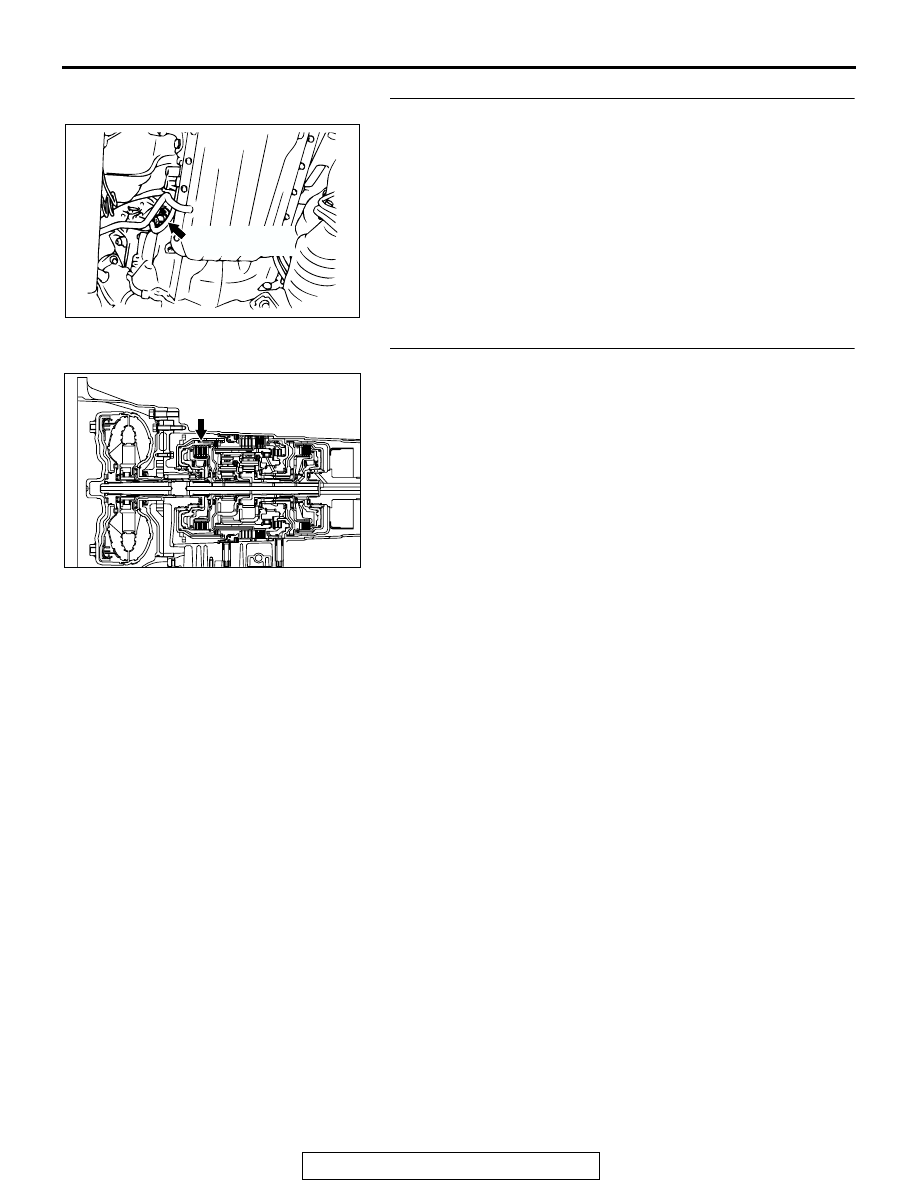
STEP 17. Replace the input shaft speed sensor.

(1) Replace the input shaft speed sensor. Refer to GROUP 

23B, Transmission 

P.23B-19

.

(2) Test drive the vehicle.
(3) Check for A/T diagnostic trouble code.
Q: Is A/T DTC 22 set?

YES : Go to Step 18.
NO :  The procedure is complete.

STEP 18. Replace the reverse clutch retainer.

(1) Replace the reverse clutch retainer. Refer to GROUP 23B, 

Reverse and Overdrive Clutches 

P.23B-54

.

(2) Test drive the vehicle.
(3) Check for A/T diagnostic trouble code.
Q: Is A/T DTC 22 set?

YES : An A/T DTC may have set due to external radio 

frequency interference (RFI) possibility caused by 
cellular phone activity, or aftermarket components 
installed on the vehicle.

NO :  The procedure is complete.

AC002609AE

INPUT SHAFT
SPEED SENSOR

AC103774AB

AUTOMATIC TRANSMISSION DIAGNOSIS

TSB Revision

AUTOMATIC TRANSMISSION

23A-90

STEP 19. Using scan tool MB991958, check data list item 
22: Input Shaft Speed Sensor.

CAUTION

To prevent damage to scan tool MB991958, always turn the 
ignition switch to the "LOCK" (OFF) position before con-
necting or disconnecting scan tool MB991958.
(1) Connect scan tool MB991958 to the data link connector.
(2) Start the engine.
(3) Set scan tool MB991958 to data-reading mode.

• Item 22: Input Shaft Speed Sensor.

• When driving at constant speed of 50 km/h (31 

mph), the display should be "1,400 

− 1,700 r/min" 

(Gear range: 3rd gear).

(4) Turn the ignition switch to the "LOCK" (OFF) position.
Q: Is the sensor operating properly?

YES : It can be assumed that this malfunction is intermittent. 

Refer to GROUP 00, How to Use 
Troubleshooting/Inspection Service Points 

− How to 

Cope with Intermittent Malfunction 

P.00-7

.

NO :  Replace the PCM.

AK303629AB

MB991911

MB991827

MB991824 

16-PIN

AUTOMATIC TRANSMISSION DIAGNOSIS

TSB Revision

AUTOMATIC TRANSMISSION

23A-91

DTC 23 (P0720): Output Shaft Speed Sensor System

Output Shaft Speed Sensor System Circuit

AUTOMATIC TRANSMISSION DIAGNOSIS

TSB Revision

AUTOMATIC TRANSMISSION

23A-92

.

CIRCUIT OPERATION

• The output shaft speed sensor generates a 0 ⇔ 

5 volt pulse signal when the output shaft rotates. 
The pulse signal frequency increases with a rise 
in output shaft speed.

• The output shaft speed sensor is connected to 

the PCM (terminals 57 and 104) via the output 
shaft speed sensor connector (terminals 1 and 
2).

• The PCM detects the output shaft speed by the 

signal input to terminal 104.

• The output shaft speed sensor generates the 

pulse signal as the teeth of the output shaft pass 
the magnetic tip of the sensor.

.

AC202387

1 2 3

CONNECTOR: B-15

B-15 (GR)

AB

AC202363

4

3

10 11

9

8

5

12

1
6

2
7

9 10

8

6 7

31 32

30

29

21

20

19

18

5

4

2

1

3

27

26

24

23

25

16

15

14

13

12

28

17

33

22

11

22

9 10

20

19

6 7 8

21

17

1516

5

14

12 13

3

2

4

18

11

1

CONNETORS: C-30, C-71, C-96

AB

C-30

C-71

C-96

C-30

C-71

C-96

AC202316

PCM

60

46

26

57

45

44

64

55 56

65

62 63

52 53

5051

61

42

59

48

41
47
58

43
49

54

120

107

119

106

129 130

118

105

117

114115116

126127128

104

111

103

112

108

101102

109110

121122123

124

113

125

CONNECTORS: C-90, C-92

AB

C-90

C-92

C-90 (GR)

C-92 (GR)

AC202365

JUNCTION BLOCK (REAR)

2

1

M

4

3

19 20

6

17

7

5

15

14

16

8

18

3

11 12

4

2

10

1

9

13

CONNECTORS: D-08, D-13

AB

D-08

D-13

D-08

D-13


Content   ..  629  630  631  632   ..