Mitsubishi Montero Sport (2004+). Manual - part 596


  Index      Mitsubishi     Mitsubishi Montero Sport - service repair manual 2004 year


Search            


Content   ..  594  595  596  597   ..


Mitsubishi Montero Sport (2004+). Manual - part 596


MANUAL A/C DIAGNOSIS

TSB Revision

HEATER, AIR CONDITIONING AND VENTILATION

55-11

INSPECTION PROCEDURE 3: When The A/C is Operating, Temperature inside the Passenger 
Compartment does not Decrease (Cool Air is not Emitted).

DIAGNOSIS

STEP 1. Check for refrigerant leaks.
Q: Is the refrigerant leaking?

YES : Repair. Then go to Step 5.
NO :  Go to Step 2.

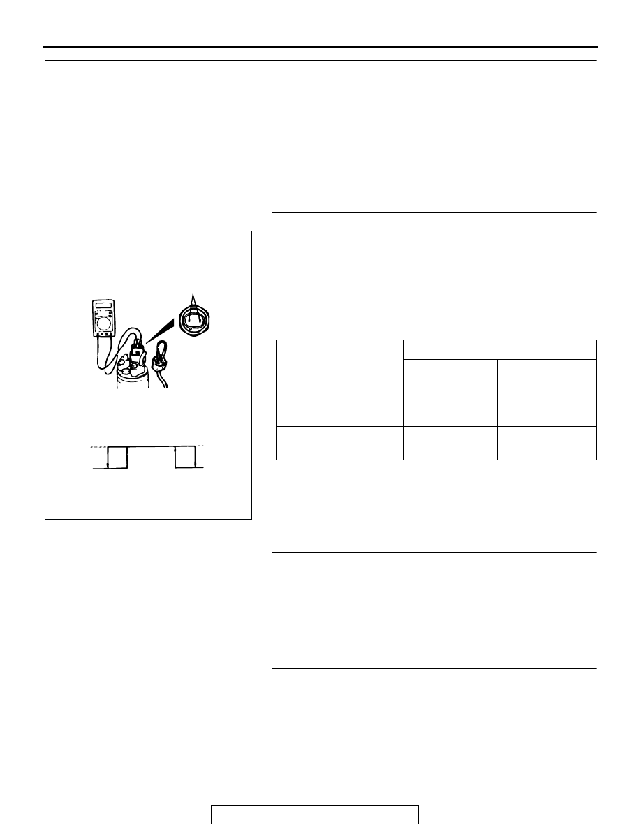
STEP 2. Check the dual pressure switch operation.

(1) Remove the dual pressure switch connector and connect 

the high/low pressure side terminals located on the harness 

side as shown in the illustration.

(2) Install a gauge manifold to the high-pressure side service 

valve of the refrigerant line. (Refer to 

P.55-29

.)

(3) When the high/low pressure sides of the dual pressure 

switch are at operation pressure (ON) and there is 
continuity between the respective terminals.

Q: When the high/low pressure sides of the dual pressure 

switch are at operation pressure (ON), is there 
continuity between the respective terminals?
YES : 
Go to Step 3.
NO :  Replace the switch. Then go to Step 5.

STEP 3. Measure the automatic compressor controller 
terminal voltage.

Refer to 

P.55-25

.

Q: Is the automatic compressor controller terminal voltage 

correct?
YES : 
Go to Step 4.
NO :  Replace. Then go to Step 5.

STEP 4. Measure the powertrain control module terminal 
voltage.

Refer to GROUP 13A, Diagnosis 

− Check at the Powertrain 

Control Module (PCM) 

P.13A-856

.

Q: Is the voltage correct?

YES : Go to Step 5.
NO :  Replace. Then go to Step 5.

ITEM

DUAL PRESSURE SWITCH

FROM OFF TO 
ON

FROM ON TO 
OFF

Low-pressure side kPa 
(psi)

221 (32.1)

196 (28.4)

High-pressure side kPa 
(psi)

2,354 (341.4)

2,942 (426.7)

A003021

HIGH/LOW
PRESSURE SIDE

LOW-PRESSURE
SIDE

HIGH-PRESSURE
SIDE

ON

OFF

ON

OFF

AB

MANUAL A/C DIAGNOSIS

TSB Revision

HEATER, AIR CONDITIONING AND VENTILATION

55-12

STEP 5. Retest the system.
Q: Does the system produce cool air?

YES : The procedure is complete. (If no malfunctions are 

found in all steps, an intermittent malfunction is 
suspected. Refer to GROUP 00, How to Use 
Troubleshooting/Inspection Service Points 

− How to 

Cope with Intermittent Malfunction 

P.00-7

.)

NO :  Go to Step 1.

INSPECTION PROCEDURE 4: Blower Fan and Motor do not Operate.

DIAGNOSIS

STEP 1. Check the blower relay continuity.

Remove the blower relay and check continuity.

Q: Is the blower relay continuity in good condition?

YES : Go to Step 2.
NO :  Replace. Then go to Step 5.

STEP 2. Check the blower fan and motor operation.

When battery voltage is applied between the terminals, check 
that the motor operates.
Q: Is there any abnormal noise?

YES : Go to Step 3.
NO :  Replace. Then go to Step 5.

BATTERY CONNECTION TESTER 

CONNECTION

SPECIFIED 
CONDITION

Not applied

− 5

Open circuit

• Connect terminal 3 to 

the positive battery 
terminal

• Connect terminal 1 to 

the negative battery 
terminal

− 5

Less than 2 
ohms

AC002841AB

BLOWER

RELAY

AC002855 AB

MANUAL A/C DIAGNOSIS

TSB Revision

HEATER, AIR CONDITIONING AND VENTILATION

55-13

STEP 3. Check the blower switch continuity.

Remove the blower switch and check continuity.

Q: Is there continuity at the blower switch?

YES : Go to Step 4.
NO :  Replace. Then go to Step 5.

STEP 4. Check the resistor resistance value.

Use an ohmmeter to measure the resistance between the ter-
minals as indicated below. Check that the measured value is at 
the standard value.

Q: Is the measured value at the standard value?

YES : Go to Step 5.
NO :  Replace. Then go to Step 5.

STEP 5. Retest the system.
Q: Do the blower fan and motor operate?

YES : The procedure is complete. (If no malfunctions are 

found in all steps, an intermittent malfunction is 
suspected. Refer to GROUP 00, How to Use 
Troubleshooting/Inspection Service Points 

− How to 

Cope with Intermittent Malfunction 

P.00-7

.)

NO :  Go to Step 1.

SWITCH 
POSITION

TESTER 
CONNECTION 

SPECIFIED 
CONDITION

At the "OFF" 
position

− 8

− 5

− 5

− 6

− 7

Open circuit

At the "LO" position 3 

− 5

− 8

Less than 2 ohms

At the "ML" position 5 

− 6

− 8

Less than 2 ohms

At the "MH" 
position

− 5

− 8

Less than 2 ohms

At the "HI" position 5 

− 7

− 8

Less than 2 ohms

AC002851AB

MEASUREMENT TERMINAL

STANDARD VALUE 

Between terminals 2 and 3 (LO) 2.0

Between terminals 3 and 4 (ML) 1.1

Between terminals 3 and 1 (MH) 0.37

AC002856AB

MANUAL A/C DIAGNOSIS

TSB Revision

HEATER, AIR CONDITIONING AND VENTILATION

55-14

INSPECTION PROCEDURE 5: Blower Fan and Motor do not Stop Operating.

DIAGNOSIS

STEP 1. Check the harness wires between the blower 
switch connector C-07 (terminal No.2, 3 and 6), blower 
resistor connector C-22 (terminal No.1, 2, 3, and 4), and the 
blower fan motor connector C-21 (terminal No.2).

Q: Are the harness wires between the blower fan and 

motor switch connector C-07 (terminal No.2, 3 and 6), 
blower resistor connector C-22 (terminal No.1, 2, 3, and 
4), and the blower fan motor connector C-21 (terminal 
No.2) in good condition?
YES : 
Go to Step 2.
NO :  Repair it. Then go to Step 4.

AC200770

AB

5

1

6

7

8

2

3

4

1

2

1
3

4

2

CONNECTOR: C-07, C-21, C-22

C-07

HARNESS SIDE

C-21

HARNESS SIDE

C-22

HARNESS SIDE

AB

C-07

C-21

C-22


Content   ..  594  595  596  597   ..