Mitsubishi Montero Sport (2004+). Manual - part 507


  Index      Mitsubishi     Mitsubishi Montero Sport - service repair manual 2004 year


Search            


Content   ..  505  506  507  508   ..


Mitsubishi Montero Sport (2004+). Manual - part 507


IGNITION SWITCH

TSB Revision

CHASSIS ELECTRICAL

54-15

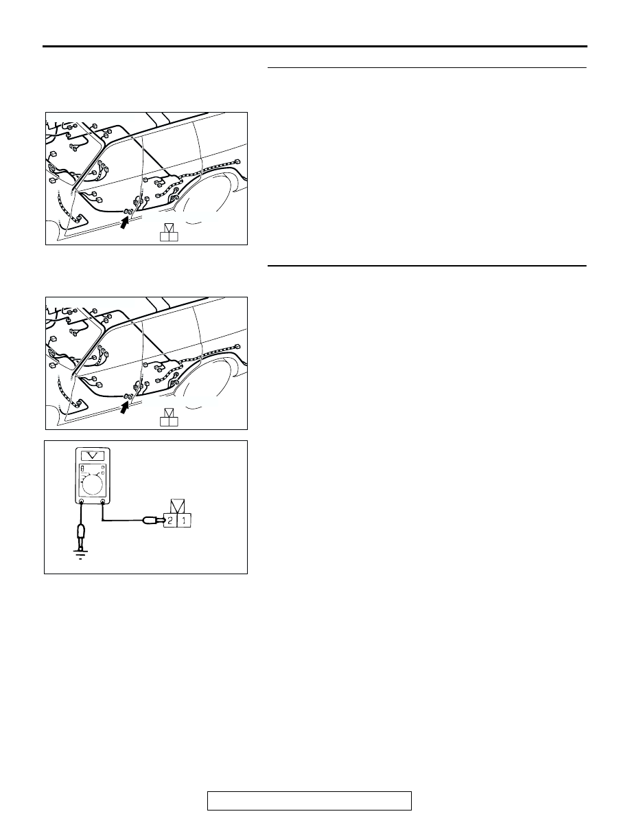
STEP 5. Check driver's side door switch connector E-33 
for loose, corroded or damaged terminals, or terminals 
pushed back in the connector.

Q: Is driver's side door switch connector E-33 damaged?

YES : Repair or replace it. Refer to GROUP 00E, Harness 

Connector Inspection 

P.00E-2

. The tachometer 

should work normally.

NO :  Go to Step 6.

STEP 6. Check the driver's side door switch connector 
E-33.

(1) Disconnect the driver's side door switch connector E-33 and 

the harness side.

(2) Measure the voltage between terminal 2 and ground.

• The measured value should be approximately 5 volts.

Q: Does the measured voltage correspond with this range?

YES : There is no action to be taken.
NO :  Go to Step 7.

AC202056

2 1

COMPONENT SIDE

CONNECTOR: E-33

AB

E-33

AC202056

2 1

COMPONENT SIDE

CONNECTOR: E-33

AB

E-33

AC002735

E-33 HARNESS CONNECTOR:
COMPONENT SIDE

AC

IGNITION SWITCH

TSB Revision

CHASSIS ELECTRICAL

54-16

STEP 7. Check the harness wires between driver's side 
door switch connector E-33 (terminal No.2) and ETACS 
connector D-11 (terminal No.9).

AC201939

1

3

4

7 6 5

2

9

11

12

10

13

8

1
8

3

4

5

7 6

10

15

16

14

12

13

11

9

2

CONNECTORS: D-11, D-14

D-11

D-14 (B)

D-11 COMPONENT SIDE

D-14 COMPONENT SIDE

AB

JUNCTION BLOCK
 (FRONT)

AC201940

2 1

8

19

7

6

5

16

15

17 18

4

3

2

10 11 12 13

1
9

14

CONNECTORS: E-33, E-42

AC

E-33 (B)

E-42

COMPONENT SIDE

E-42

IGNITION SWITCH

TSB Revision

CHASSIS ELECTRICAL

54-17

NOTE: After inspecting junction block connector D-14 and 
intermediate connector E-42, inspect the wire. If junction block 
connector D-14 and intermediate connector E-42 are dam-
aged, repair or replace them. Refer to GROUP 00E, Harness 
Connector Inspection 

P.00E-2

.

Q: Are the harness wires between driver's side door switch 

connector E-33 (terminal No.2) and ETACS connector 
D-11 (terminal No.9) in good condition?
YES : 
Go to Step 8.
NO :  Repair them. Then check that the malfunction is 

eliminated.

STEP 8. Check the ignition key hole illumination light 
input.

(1) Remove the driver's under cover (Refer to 

P.52A-37

).

(2) Remove the lower and upper column covers (Refer to 

P.52A-37

).

(3) Disconnect wiring connector D-16 from the key reminder 

switch and measure at the switch side.

(4) Connect a vehicle battery as shown, and then check the 

ignition key hole illumination light illuminates.

Q: Does the situation key hole illumination light 

illuminate?
YES : 
Go to Step 9.
NO :  Replace the key reminder switch.

AC202060

4

5

3

1

6

7

2

1
3

2
7

6

5

4

+

-

AC102749

CONNECTOR: D-16

AB

IGNITION SWITCH

TSB Revision

CHASSIS ELECTRICAL

54-18

STEP 9. Check the power supply for the ignition key hole 
illumination light.

(1) Disconnect the key reminder switch connector D-16 and 

measure at the harness side.

(2) Measure the voltage between terminal 1 and ground.

• The measured value should be approximately 12 volts 

(battery positive voltage).

Q: Is the measured voltage within this specified range?

YES : Go to Step 11.
NO :  Go to Step 10.

STEP 10. Check connector D-16 at the key reminder switch 
for damage.

Q: Is key reminder switch connector D-16 in good 

condition?
YES : 
Go to Step 11.
NO :  Replace it. Then check that the malfunction is 

eliminated.

STEP 11. Check the harness wires between fusible link 
number 8 and key reminder switch connector D-16 

(terminal No.1).

AC202060

4

5

3

1

6

7

2

AC309477     

D-16 HARNESS CONNECTOR:
COMPONENT SIDE

AB

AC202060

4

5

3

1

6

7

2

AC202060

4

5

3

1

6

7

2


Content   ..  505  506  507  508   ..