Mitsubishi Montero Sport (2004+). Manual - part 432


  Index      Mitsubishi     Mitsubishi Montero Sport - service repair manual 2004 year


Search            


Content   ..  430  431  432  433   ..


Mitsubishi Montero Sport (2004+). Manual - part 432


DIFFERENTIAL CARRIER ASSEMBLY

TSB Revision

REAR AXLE

27-29

.

<<B>> DIFFERENTIAL CARRIER REMOVAL

CAUTION

Use care not to strike the companion flange.
Remove the attaching nuts. Strike the lower part of differential 
carrier assembly with a piece of wood several times to loosen 
the assembly. Remove the assembly.

INSTALLATION SERVICE POINT

.

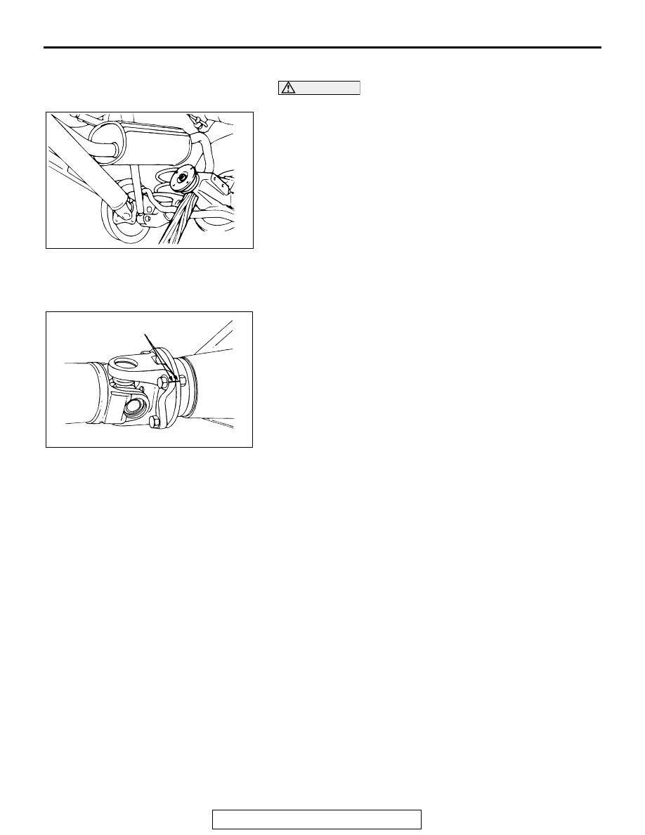
>>A<< PROPELLER SHAFT INSTALLATION
Align the mating marks on the flange yoke and the companion 
flange to install the propeller shaft.

AC004904 AB

AC003833 AB

MATING MARKS

DIFFERENTIAL CARRIER ASSEMBLY

TSB Revision

REAR AXLE

27-30

DISASSEMBLY

M1272002200225

CAUTION

Do not disassemble the limited slip differential case assembly.

AC309414

AB

<LIMITED SLIP DIFFERENTIAL>

<CONVENTIONAL DIFFERENTIAL>

4

5

6

13

10

9

11

12

8 7

14

6

5

2

1

13

12

10

11

28

1

2

20

19

21 22

23

18

5 6

7

15

6 5

2

4

1

1

2

3

3

29

27

25

26

17

24

16

N

N

DISASSEMBLY STEPS

<<A>>

• INSPECTION BEFORE 

DISASSEMBLY

1. LOCK PLATE

<<B>>

2. SIDE BEARING NUT
3. BEARING CAP

<<C>>

4. DIFFERENTIAL CASE ASSEMBLY
5. SIDE BEARING OUTER RACE

<<D>>

6. SIDE BEARING INNER RACE

<<E>>

7. DRIVE GEAR

<<F>>

8. LOCK PIN
9. PINION SHAFT
10. PINION GEAR
11. PINION WASHER
12. SIDE GEAR
13. SIDE GEAR THRUST SPACER
14. DIFFERENTIAL CASE
15. LIMITED SLIP DIFFERENTIAL CASE 

ASSEMBLY

<<G>>

16. SELF-LOCKING NUT
17. WASHER

<<H>>

18. DRIVE PINION ASSEMBLY
19. DRIVE PINION FRONT SHIM (FOR 

ADJUSTING PRELOAD OF DRIVE 
PINION)

20. DRIVE PINION SPACER

<<I>>

21. DRIVE PINION REAR BEARING 

INNER RACE

22. DRIVE PINION REAR SHIM (FOR 

ADJUSTING DRIVE PINION 
HEIGHT)

23. DRIVE PINION

<<H>>

24. COMPANION FLANGE

<<J>>

25. OIL SEAL

<<J>>

26. DRIVE PINION FRONT BEARING 

INNER RACE

<<J>>

27. DRIVE PINION FRONT BEARING 

OUTER RACE

<<K>>

28. DRIVE PINION REAR BEARING 

OUTER RACE

29. DIFFERENTIAL CARRIER

DISASSEMBLY STEPS (Continued)

DIFFERENTIAL CARRIER ASSEMBLY

TSB Revision

REAR AXLE

27-31

Required Special Tools:

• MB990810: Side Bearing Puller

• MB990850: End Yoke Holder

• MB990939: Brass Bar

• MB991367: Special Spanner

• MB991385: Pin

• MB991407: Differential Rear Support Arbor

• MD998801: Bearing Remover

DISASSEMBLY SERVICE POINTS

.

<<A>> INSPECTION BEFORE DISASSEMBLY
Except for the following standard values, inspection procedure 
is the same as GROUP 26, inspection before disassembly 

P.26-41

.

DRIVE GEAR BACKLASH

Standard value: 0.13 

 0.18 mm (0.005  0.007 in)

DIFFERENTIAL GEAR BACKLASH

Standard value: 0 

 0.076 mm (0  0.0030 in)

.

<<B>> SIDE BEARING NUT REMOVAL
Use special tools MB991367 and MB991385, remove the side 
bearing nut.
NOTE: Keep the right and left side bearings and side bearing 
nuts separate, so that they do not become mixed at the time of 
assembly.

.

<<C>> DIFFERENTIAL CASE ASSEMBLY REMOVAL

CAUTION

When taking out the differential case assembly, be careful 
not to drop and damage the differential side shims or the 
side bearing outer races.
Use the wooden handle of a hammer to remove the differential 
case assembly, differential side shims and side bearings.
NOTE: Keep the right and left side bearings and side bearing 
outer race separated, so that they do not become mixed at the 
time of assembly.

.

AC004921AB

MB991385

MB991367

ACX02422

DIFFERENTIAL CARRIER ASSEMBLY

TSB Revision

REAR AXLE

27-32

<<D>> SIDE BEARING INNER RACE REMOVAL
Use special tools MB990810 and MB991407 to pull out the side 
bearing inner race.
NOTE: Attach the prongs of special tools MB990810 and 
MB991407 to the inner race of the side bearing through the 
openings in the differential case.

.

<<E>> DRIVE GEAR REMOVAL
1. Make mating marks to the differential case and the drive 

gear.

2. Loosen the drive gear attaching bolts in diagonal sequence 

to remove the drive gear.

.

<<F>> LOCK PIN REMOVAL
Drive out the lock pin with a punch.

.

<<G>> SELF-LOCKING NUT REMOVAL
Use special tool MB990850 to hold the companion flange, and 
then remove the companion flange self-locking nut.

.

AC203814 AC

MB990810

MB991407

ACX01042AB

MATING 
MARKS

ACX01048AB

PUNCH

ACX01043AB

MB990850


Content   ..  430  431  432  433   ..