Mitsubishi Montero Sport (2004+). Manual - part 363
MULTIPORT FUEL INJECTION (MFI) DIAGNOSIS
TSB Revision
MULTIPORT FUEL INJECTION (MFI)
13A-865
CAMSHAFT POSITION SENSOR AND
CRANKSHAFT POSITION SENSOR
Required Special Tools:
• MB991348: Test Harness Set
• MD998478: Test Harness
.
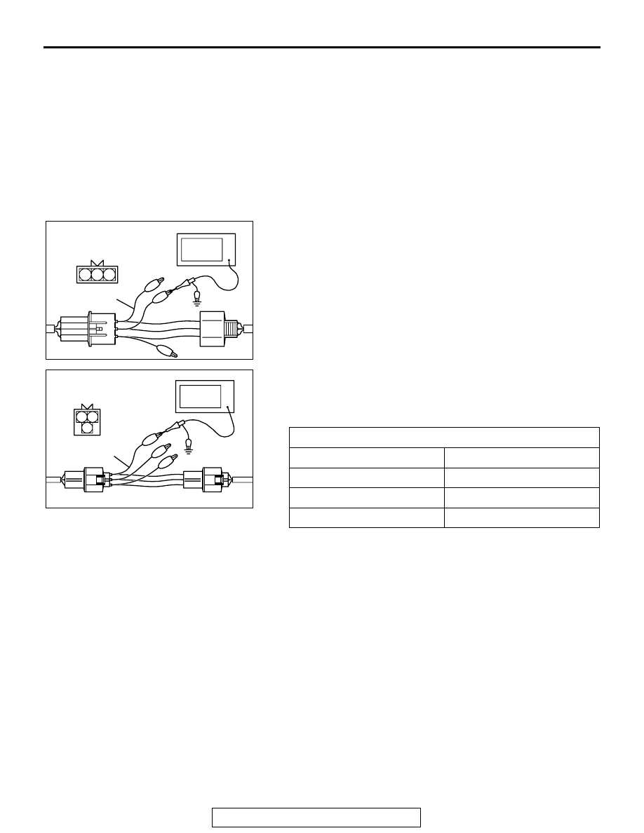
Measurement Method
1. Disconnect the camshaft position sensor intermediate
connector, and connect the test harness special tool
(MB991348) in between. (All terminals should be
connected.)
2. Connect the oscilloscope probe to camshaft position sensor
intermediate connector terminal No. 2.
3. Disconnect the crankshaft position sensor connector, and
connect the test harness special tool (MD998478) in
between.
4. Connect the oscilloscope probe to crankshaft position
sensor connector terminal No. 2 (black clip of special tool).
.
Alternate method (Test harness not available)
1. Connect the oscilloscope probe to PCM terminal No. 56.
(Check the camshaft position sensor signal wave pattern.)
2. Connect the oscilloscope probe to PCM terminal No. 45.
(Check the crankshaft position sensor signal wave pattern.)
Standard Wave Pattern
Observation conditions
Function
Special pattern
Pattern height
Low
Pattern selector
Display
Engine r/min
Idle speed
AK102978AB
1 2 3
OSCILLOSCOPE
MB991348
CAMSHAFT POSITION
SENSOR INTERMEDIATE
CONNECTOR
AK102979AB
MD998478
1 2
3
CRANKSHAFT POSITION
SENSOR CONNECTOR
OSCILLOSCOPE