Mitsubishi Montero Sport (2004+). Manual - part 330


  Index      Mitsubishi     Mitsubishi Montero Sport - service repair manual 2004 year


Search            


Content   ..  328  329  330  331   ..


Mitsubishi Montero Sport (2004+). Manual - part 330


MULTIPORT FUEL INJECTION (MFI) DIAGNOSIS

TSB Revision

MULTIPORT FUEL INJECTION (MFI)

13A-733

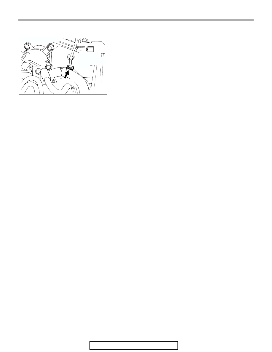
STEP 5. Check the ignition system.
(1) Connect the tachometer to engine speed detection 

connector A-37 (terminal No. 1).

(2) Crank the engine.

• The tachometer should indicate cranking speed.

(3) Turn the ignition switch to the "LOCK" (OFF) position.
Q: Is the cranking speed normal?

YES : Go to Step 6.
NO :  Refer to INSPECTION PROCEDURE 31 

− Ignition 

Circuit System 

P.13A-828

.

STEP 6. Check the ignition timing.
(1) Check the ignition timing at cranking.

Standard value: 5

° BTDC ± 3°

Q: Is the ignition timing normal?

YES : Go to Step 7.
NO :  Check that the crankshaft position sensor and timing 

belt cover are in the correct position. Then confirm 
that the malfunction symptom is eliminated.

AK200042

1

AB

CONNECTOR: A-37

A-37(L)

HARNESS 
CONNECTOR:
COMPONENT 
SIDE

MULTIPORT FUEL INJECTION (MFI) DIAGNOSIS

TSB Revision

MULTIPORT FUEL INJECTION (MFI)

13A-734

STEP 7. Measure the injector resistance at injector 
intermediate connector A-04.
(1) Disconnect the injector intermediate connector A-04.

(2) Measure the resistance between each male connector side 

terminal.

a. Measure the resistance between terminal No. 8 and No. 

3 when measuring No. 1 cylinder injector

b. Measure the resistance between terminal No. 8 and No. 

2 when measuring No. 2 cylinder injector

c. Measure the resistance between terminal No. 8 and No. 

1 when measuring No. 3 cylinder injector

d. Measure the resistance between terminal No. 8 and No. 

7 when measuring No. 4 cylinder injector

e. Measure the resistance between terminal No. 8 and No. 

6 when measuring No. 5 cylinder injector

f. Measure the resistance between terminal No. 8 and No. 

5 when measuring No. 6 cylinder injector

• Resistance should be between 13 and 16 ohms [at 20°C 

(68

°F)].

Q: Is the resistance normal?

YES : Go to Step 10.
NO :  Go to Step 8.

AK200014

7

2 1
6 5

4 3
8

CONNECTOR: A-04

AB

FEMALE SIDE 
CONNECTOR

A-04(B)

AK000542

6

3 4
7 8

1 2
5

INJECTOR
INTERMEDIATE
CONNECTOR

AB

MULTIPORT FUEL INJECTION (MFI) DIAGNOSIS

TSB Revision

MULTIPORT FUEL INJECTION (MFI)

13A-735

STEP 8. Check the injector.
(1) Disconnect the injector connector, which deviates from the 

standard value at Step 7.

(2) Measure the resistance between injector side connector 

terminal No. 1 and No. 2.

Standard value: 13 

 16 ohms [at 20°C (68°F)]

Q: Is the resistance between 13 and 16 ohms [at 20

°

(68

°F)]?

YES : Go to Step 9.
NO :  Replace the injector. Then confirm that the 

malfunction symptom is eliminated.

STEP 9. Check harness connector A-70 or A-71 or A-72 or 
A-73 or A-74 or A-75 at injector for damage.
 Check the injector connector, which deviates from the standard 
value at Step 7.
Q: Is the harness connector in good condition?

YES : Repair harness wire between injector intermediate 

connector and injector connector because of harness 
damage. Then confirm that the malfunction symptom 
is eliminated.

NO :  Repair or replace it. Refer to GROUP 00E, Harness 

Connector Inspection 

P.00E-2

. Then confirm that the 

malfunction symptom is eliminated.

STEP 10. Check harness connector A-04 at injector 
intermediate connector for damage.
Q: Is the harness connector in good condition?

YES : Go to Step 11.
NO :  Repair or replace it. Refer to GROUP 00E, Harness 

Connector Inspection 

P.00E-2

. Then confirm that the 

malfunction symptom is eliminated.

AK200022

1

2

AB

CONNECTORS: A-70, A-71, A-72, A-73, A-74, 
                            A-75

A-70(GR)

A-71(GR)

A-72(GR)

HARNESS CONNECTOR: 
COMPONENT SIDE

A-73(GR)

A-74(GR)

A-75(GR)

AK000456

1 2

INJECTOR SIDE
CONNECTOR

AB

AK200022

1

2

AB

CONNECTORS: A-70, A-71, A-72, A-73, A-74, 
                            A-75

A-70(GR)

A-71(GR)

A-72(GR)

HARNESS CONNECTOR: 
COMPONENT SIDE

A-73(GR)

A-74(GR)

A-75(GR)

AK200014

7

2 1
6 5

4 3
8

CONNECTOR: A-04

AB

FEMALE SIDE 
CONNECTOR

A-04(B)

MULTIPORT FUEL INJECTION (MFI) DIAGNOSIS

TSB Revision

MULTIPORT FUEL INJECTION (MFI)

13A-736

STEP 11. Check harness connector C-89 at PCM for 
damage.
Q: Is the harness connector in good condition?

YES : Go to Step 12.
NO :  Repair or replace it. Refer to GROUP 00E, Harness 

Connector Inspection 

P.00E-2

. Then confirm that the 

malfunction symptom is eliminated.

STEP 12. Check for harness damage between injector 
intermediate connector A-04 and PCM connector C-89.

a. Check the harness wire between injector intermediate con-

nector A-04 (terminal No. 3) and PCM connector C-89 (ter-
minal No. 1) when checking No. 1 cylinder injector.

b. Check the harness wire between injector intermediate con-

nector A-04 (terminal No. 2) and PCM connector C-89 (ter-
minal No. 9) when checking No. 2 cylinder injector.

c. Check the harness wire between injector intermediate con-

nector A-04 (terminal No. 1) and PCM connector C-89 (ter-
minal No. 24) when checking No. 3 cylinder injector.

d. Check the harness wire between injector intermediate con-

nector A-04 (terminal No. 7) and PCM connector C-89 (ter-
minal No. 2) when checking No. 4 cylinder injector.

e. Check the harness wire between injector intermediate con-

nector A-04 (terminal No. 6) and PCM connector C-89 (ter-
minal No. 10) when checking No. 5 cylinder injector.

f. Check the harness wire between injector intermediate con-

nector A-04 (terminal No. 5) and PCM connector C-89 (ter-
minal No. 25) when checking No. 6 cylinder injector.

Q: Is the harness wire in good condition?

YES : Check the following items, and repair or replace the 

defective items.

a. Check the ignition coil, spark plugs, spark plug 

cables.

b. Check if the injectors are clogged.

c. Check if fuel is contaminated.

d. Check compression.

Then confirm that the malfunction symptom is 

eliminated.

NO :  Repair it. Then confirm that the malfunction symptom 

is eliminated.

AK103914

2

3

4

5

6

7

8

9

11

12

13

14

15

16

17

18

19

20

30

21

22

23

24

25

26

27

28

29

31

32

33

34

35

1

10

AB

CONNECTOR: C-89

C-89(GR)

HARNESS CONNECTOR:
COMPONENT SIDE

AK200014

7

2 1
6 5

4 3
8

CONNECTOR: A-04

AB

FEMALE SIDE 
CONNECTOR

A-04(B)

AK103914

2

3

4

5

6

7

8

9

11

12

13

14

15

16

17

18

19

20

30

21

22

23

24

25

26

27

28

29

31

32

33

34

35

1

10

AB

CONNECTOR: C-89

C-89(GR)

HARNESS CONNECTOR:
COMPONENT SIDE


Content   ..  328  329  330  331   ..