Mitsubishi Montero Sport (2004+). Manual - part 320
MULTIPORT FUEL INJECTION (MFI) DIAGNOSIS
TSB Revision
MULTIPORT FUEL INJECTION (MFI)
13A-693
.
CIRCUIT OPERATION
• A 5-volt voltage is supplied to the barometric
pressure sensor power terminal (terminal No. 1)
from the PCM (terminal No. 46). The ground ter-
minal (terminal No. 5) is grounded with PCM (ter-
minal No. 57).
• A voltage that is proportional to the atmospheric
pressure is sent to the PCM (terminal No. 55)
from the barometric pressure sensor output ter-
minal (terminal No. 2).
.
TECHNICAL DESCRIPTION
• The barometric pressure sensor outputs a volt-
age which corresponds to the barometric pres-
sure.
• The PCM checks whether this voltage is within a
specified range.
.
DESCRIPTIONS OF MONITOR METHODS
Barometric pressure sensor output voltage is out of
reasonable barometric pressure range.
.
MONITOR EXECUTION
Continuous
.
MONITOR EXECUTION CONDITIONS (Other
monitor and Sensor)
Other Monitor (There is no temporary DTC stored
in memory for the item monitored below)
• Not applicable
Sensor (The sensor below is determined to be
normal)
• Not applicable
.
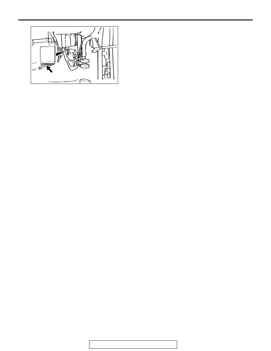
AK103738AC
CONNECTOR: C-90
PCM
C-90(GR)